
High-voltage battery charging system and charger with such charging system

a charging system and high-voltage battery technology, applied in charging stations, electric vehicle charging technology, transportation and packaging, etc., can solve the problems of depletion of world's oil supply, pollution of the air by waste gases, carbon dioxide, etc., and achieve the effect of high charging voltage and enhanced reliability of the high-voltage battery charging system

Inactive Publication Date: 2013-04-11
DELTA ELECTRONICS INC
View PDF7 Cites 30 Cited by
  • Summary
  • Abstract
  • Description
  • Claims
  • Application Information

AI Technical Summary

Benefits of technology

The present invention provides a high-voltage battery charging system for electric vehicles that can charge a high-voltage battery unit with a wide range of high charging voltage. The system is designed to be reliable even if the input voltage is abnormal or interrupted, and the bus capacitor is replaceable. This helps to improve the performance and reliability of electric vehicles.

Problems solved by technology

The waste gases may pollute the air.
In addition, carbon dioxide is considered to be a major cause of the enhanced greenhouse effect.
It is estimated that the world's oils supply would be depleted in the next several decades.
The oil depletion may lead to global economic crisis.
Since the bus capacitor with the high rated voltage value is difficultly available and costly, it is not easy to widen the range of the high charging voltage.
If the input voltage received by the power factor correction circuit is abnormal or interrupted, the power factor correction circuit fails to generate the bus voltage.
Under this circumstance, the auxiliary power circuit is disabled and fails to provide electric energy to various controlling units, the functions controlled by these controlling units will be lost.
Moreover, the bus capacitor of the charger for the electric vehicle is usually non-replaceable.
In other words, the conventional high-voltage battery charging system is neither cost-effective nor resource-saving.

Method used


Image

  • High-voltage battery charging system and charger with such charging system
  • High-voltage battery charging system and charger with such charging system
  • High-voltage battery charging system and charger with such charging system

Examples


Embodiment Construction

[0017]The present invention will now be described more specifically with reference to the following embodiments. It is to be noted that the following descriptions of preferred embodiments of this invention are presented herein for purpose of illustration and description only. It is not intended to be exhaustive or to be limited to the precise form disclosed.

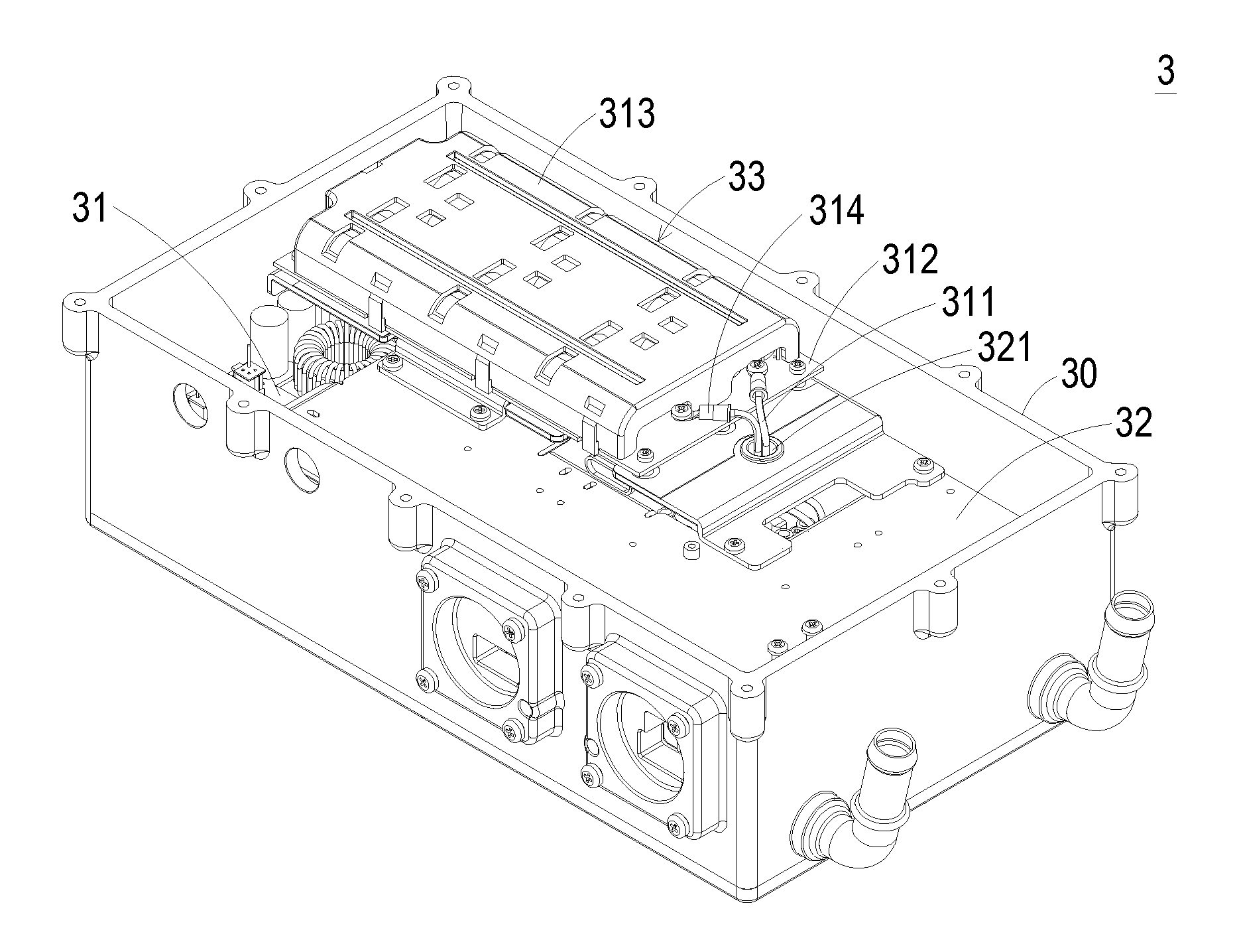
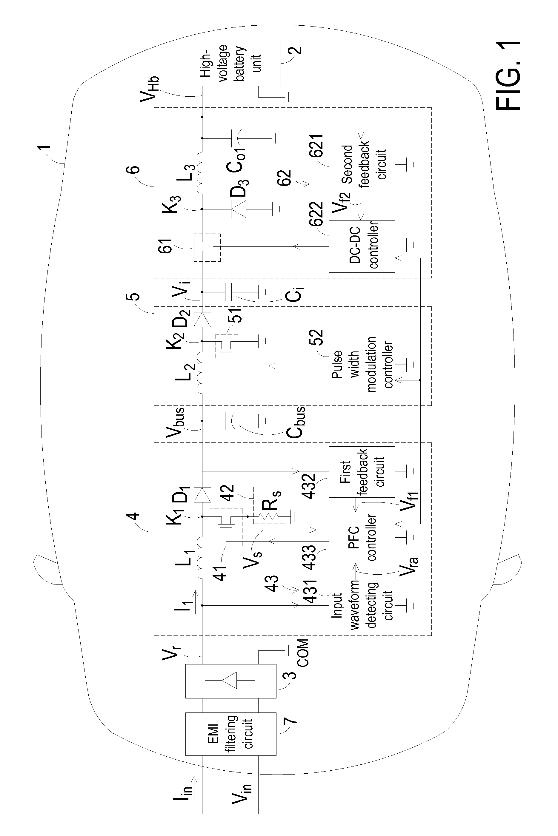
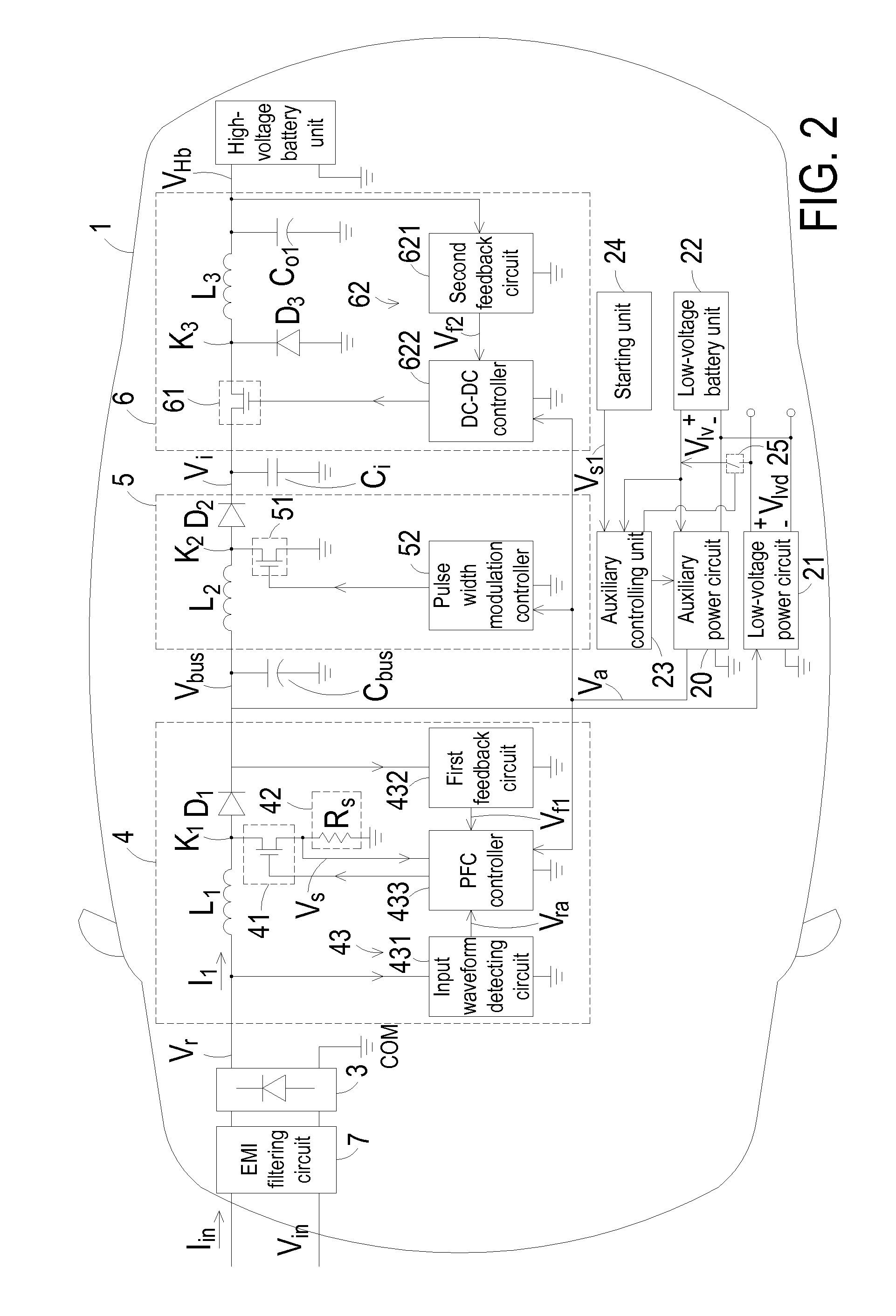
[0018]FIG. 1 is a schematic circuit block diagram illustrating the architecture of a high-voltage battery charging system according to an embodiment of the present invention. The high-voltage battery charging system is applied to and installed in an electric vehicle body 1. The high-voltage battery charging system is used for receiving electric energy of an AC input voltage Vin from an utility power source, and charging a high-voltage battery unit 2. As shown in FIG. 1, the high-voltage battery charging system comprises a rectifier circuit 3, a power factor correction circuit 4, an intermediate non-isolated DC-DC converting circu...


PUM


Abstract

A high-voltage battery charging system includes a rectifier circuit, a power factor correction circuit, a bus capacitor, an intermediate non-isolated DC-DC converting circuit, an intermediate output capacitor, and a non-isolated DC-DC converting circuit. The rectifier circuit is used for rectifying an AC input voltage into a rectified voltage. The power factor correction circuit is used for increasing a power factor of the rectified voltage and generating a bus voltage. The bus capacitor is used for energy storage and voltage stabilization. The intermediate non-isolated DC-DC converting circuit is used for boosting the bus voltage into an intermediate output voltage. The intermediate output capacitor is connected between an output terminal of the intermediate non-isolated DC-DC converting circuit and the common terminal COM for energy storage and voltage stabilization. The non-isolated DC-DC converting circuit is used for converting the intermediate output voltage into a high charging voltage, thereby charging the high-voltage battery unit.

Description

FIELD OF THE INVENTION[0001]The present invention relates to a high-voltage battery charging system, and more particularly to a high-voltage battery charging system for use in an electric vehicle. The present invention relates to a charger with such a high-voltage battery charging system.BACKGROUND OF THE INVENTION[0002]Fossil fuels such as petroleum and coal are widely used in automobiles or power plants for generating motive force or electrical power. As known, burning fossil fuels produces waste gases and carbon oxide. The waste gases may pollute the air. In addition, carbon dioxide is considered to be a major cause of the enhanced greenhouse effect. It is estimated that the world's oils supply would be depleted in the next several decades. The oil depletion may lead to global economic crisis.[0003]Consequently, there are growing demands on clean and renewable energy. Recently, electric vehicles and plug-in hybrid electric vehicles have been researched and developed. Electric veh...

Claims


Application Information

Patent Timeline
IPC IPC(8): H02J7/00H02J7/02
CPCB60L11/1811H02M1/4225H02M3/1582B60L2210/30H02M2001/007Y02T10/92Y02T10/7241Y02T90/14Y02T90/127H02J2007/10H02J7/022Y02T10/7005Y02T10/7072B60L53/20H02J7/02H02J2207/20Y02T10/72Y02T10/70H02M1/007Y02T90/12
Inventor CHEN, CHIN-HOUTANG, BO-WENCHO, MENG-FU
Owner DELTA ELECTRONICS INC
Learn More