Multi-feed antenna apparatus and methods

a multi-feed antenna and antenna technology, applied in the direction of antennas, antenna earthing switches, radiating element structural forms, etc., can solve the problems of inability to support the various specific band pair implementations of single-feed rf front-ends, additional circuitry is required,

Active Publication Date: 2013-04-11
PULSE FINLAND
View PDF8 Cites 64 Cited by
  • Summary
  • Abstract
  • Description
  • Claims
  • Application Information

AI Technical Summary

Benefits of technology

[0018]In another embodiment, the matching network includes first, second and third matching circuits configured to couple a radio frequency transceiver to first, second, and third feeds, respectively, and the first, second, and third matching circuits each provide impedance matching to a feed structure of the transceiver by at least increasing input resistance of the first, second, and third feeds.

Problems solved by technology

Therefore, by increasing the number of modes of operation supported by the device, additional circuitry is required, which is problematic given both the increasing size constraints of mobile radio devices, and the desire for reduced cost and greater simplicity (for, e.g., reliability).
Different matching would be required for different combinations of inter-band carrier aggregation pairs, therefore making single-feed RF front-end impractical to support the various specific band pair implementations.

Method used


Image

  • Multi-feed antenna apparatus and methods
  • Multi-feed antenna apparatus and methods
  • Multi-feed antenna apparatus and methods

Examples


example 1

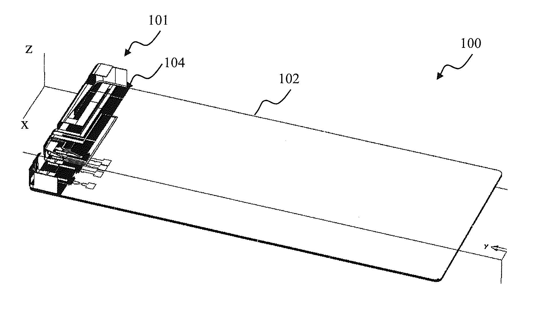
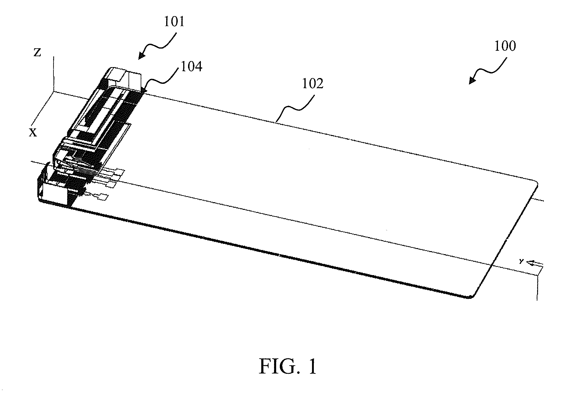
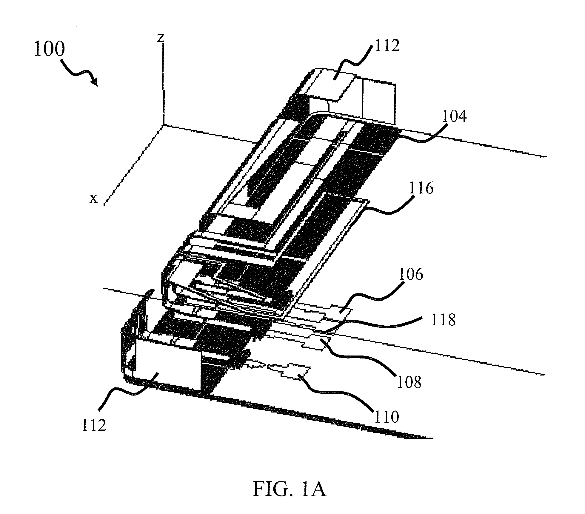
[0075]Feed port 106: LB (PILA), feed port 108: 2.5-23 GHz (PILA), feed port 110: HB (PILA). This configuration provides sufficient feed to radiator isolation between the feed ports 108 and 110 due to a wide frequency gap (about 200 MHz) between the feed port 108 and 110 frequency bands.

example 2

[0076]Feed port 106: LB (PILA), feed port 108: 2.3-2.7 GHz (PILA), feed port 110: HB (PILA). This configuration does not provide sufficient feed to radiator isolation between the feed ports 108 and 110 due to a small frequency gap (about few MHz) between the feed port 108 and 110 frequency bands.

example 3

[0077]Feed port 106: LB (PILA), feed port 108: 2.3-2.7 GHz (Loop), feed port 110: HB (PILA). This configuration provides very good feed to radiator isolation for all feed ports in all frequency bands despite a small frequency gap between the feed ports 108 and 110 frequency bands.

[0078]In one embodiment, the matching circuits for the first and third feed ports are realized through use of tapped inductors 310, 314, respectively. The inductor 310, 314 are implemented, in one variant, as narrow conductive traces on the PCB, configured to achieve the desired inductance values. In another variant, the inductors 310, 314 are implemented using discrete components, e.g. chip inductors, wound toroids, ceramic multilayer, and wire-wound inductors, etc. Residual reactance of the circuits 302, 304 can be tuned with the shunt capacitors 312, 316, respectively, so as to create a dual resonance type of response in the first and third feed ports 106, 108. The matching circuit 308, corresponding to ...


PUM


Abstract

A space efficient multi-feed antenna apparatus, and methods for use in a radio frequency communications device. In one embodiment, the antenna assembly comprises three (3) separate radiator structures disposed on a common antenna carrier. Each of the three antenna radiators is connected to separate feed ports of a radio frequency front end. In one variant, the first and the third radiators comprise quarter-wavelength planar inverted-L antennas (PILA), while the second radiator comprises a half-wavelength grounded loop-type antenna disposed in between the first and the third radiators. The PILA radiators are characterized by radiation patterns having maximum radiation axes that are substantially perpendicular to the antenna plane. The loop radiator is characterized by radiation pattern having axis of maximum radiation that is parallel to the antenna plane. The above configuration of radiating patterns advantageously isolates the first radiator structure from the third radiator structure in at least one frequency band.

Description

COPYRIGHT[0001]A portion of the disclosure of this patent document contains material that is subject to copyright protection. The copyright owner has no objection to the facsimile reproduction by anyone of the patent document or the patent disclosure, as it appears in the Patent and Trademark Office patent files or records, but otherwise reserves all copyright rights whatsoever.FIELD OF THE INVENTION[0002]The present invention relates generally to antenna apparatus for use within electronic devices such as wireless radio devices, and more particularly in one exemplary aspect to a multi-band long term evolution (LTE) or LTE-Advanced antenna, and methods of tuning and utilizing the same.DESCRIPTION OF RELATED TECHNOLOGY[0003]Internal antennas are an element found in most modern radio devices, such as mobile computers, mobile phones, Blackberry® devices, smartphones, personal digital assistants (PDAs), or other personal communication devices (PCDs). Typically, these antennas comprise a...

Claims


Application Information

Patent Timeline
Patent Type & Authority Applications(United States)
IPC IPC(8): H01Q21/24H01Q1/50H01Q1/52H01Q9/04
CPCH01Q1/243H01Q5/40H01Q9/42H01Q7/00H01Q13/10
Inventor RAMACHANDRAN, PRASADHRAAPPANA, ARIANNAMAA, PETTERI
Owner PULSE FINLAND
Why Eureka
Try Eureka