Functional Near Infrared Spectroscopy Imaging System and Method

a near infrared spectroscopy and imaging system technology, applied in the field of measurement and monitoring of near infrared images, can solve the problems of large equipment racks, inconvenient operation, and inconvenient operation of prior art systems,

Active Publication Date: 2013-04-11
BOARD OF RGT THE UNIV OF TEXAS SYST
View PDF4 Cites 38 Cited by
  • Summary
  • Abstract
  • Description
  • Claims
  • Application Information

AI Technical Summary

Problems solved by technology

These prior art systems suffer from a number of deficiencies.
A first deficiency is in the size and portability of the system.
Such a system would require a fairly large rack of equipment and substantial space to operate.
Furthermore, the sheer numbers and cost of the electronics become prohibitively large.
Second, prior art systems operate at frame rates of about 2.5 Hz or less, at low resolutions and small coverage areas.
However, these prior art systems only provide images of the spectral response of the tissue area and depth illuminated as a whole without regard for localized photonic excitation and scattering.
As a result, lateral and depth spatial resolutions as well as image contrast of these systems remain limited.

Method used


Image

  • Functional Near Infrared Spectroscopy Imaging System and Method
  • Functional Near Infrared Spectroscopy Imaging System and Method
  • Functional Near Infrared Spectroscopy Imaging System and Method

Examples


first embodiment

[0054]FIG. 3 is a block diagram of an fNIRS system according to a

[0055]FIG. 4 is diagram of a section of an elastomeric cap of a preferred embodiment.

[0056]FIG. 5 is a calibration table related to the optical transmission.

[0057]FIG. 6 is a calibration table related to the optical detection.

[0058]FIG. 7 is a flow chart for the overall operation of an fNIRS system.

[0059]FIG. 8 is a flow chart of a calibration method.

[0060]FIG. 9 is block diagram depicting the mathematical operations related to a processing method.

[0061]FIG. 10 is a flow chart of an optical detection and processing method used during operation of an fNIRS system.

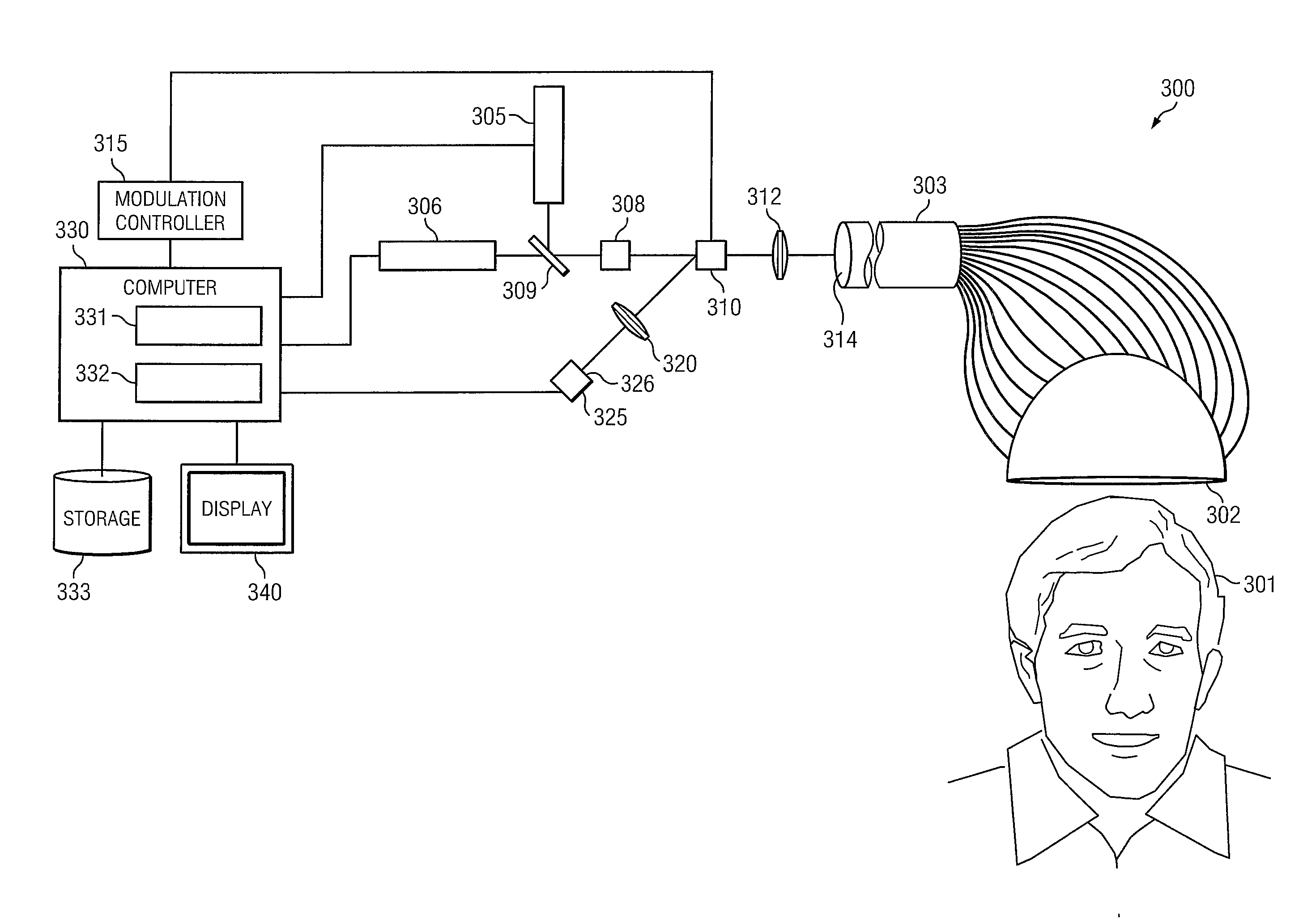
[0062]FIG. 11 is a block diagram of an fNIRS according to an alternate embodiment.

DETAILED DESCRIPTION

[0063]Disclosed are a system and method for functional near infrared spectroscopy (fNIRS) that is useful for hemodynamics and provides a significant improvement over the prior art in resolution and frame rate of images.

[0064]Referring to FIG. 3, an fNIRS system...

second embodiment

[0100]FIG. 11 shows an fNIRS system 300. The system comprises two light sources: light source 305 operating at a first wavelength, λ1 and light source 306 operating at a second wavelength λ2, beam combiner 309 for combining a light beam from light source 305 with a light beam from light source 306 into a transmit beam, collimator 308 for expanding and collimating the transmit beam, bidirectional fiber bundle 303, spatial light modulator 310 for modulating multiple portions of the transmit beam, lens system 312 for focusing the multiple portions of the transmit beam onto multiple fibers of bidirectional fiber bundle 303 at optical termination plane 314, elastomeric cap 302 on which bidirectional fiber bundle 303 is fastened and optically terminated near the skull of patient 301, photodetector array 325, imaging system 320 for imaging the optical termination plane 314 of bidirectional fiber bundle 303 onto photodetector array 325, computer 330 for processing images, a display 340 for ...


PUM


Abstract

Disclosed is a functional NIRS imaging system including an elastomeric cap, a set of transmit optical fibers and a set of receive optical fibers terminating on the inside surface of the elastomeric cap. A pair of light sources combines to produce a collimated light beam at two wavelengths. An optical modulation system, converts the light beam into a plurality of probe light beams, modulates the plurality of probe light beams and directs each probe light beam into a transmit fiber. An optical detection system accepts scattered photons from subcutaneous tissue underneath the elastomeric cap as a plurality of collected light beams and converts them into a time series of electronic images, stores the electronic images into the memory and processes the electronic images using. The system displays the resulting image on a display as a hemoglobin oxygen saturation map.

Description

CROSS-REFERENCE TO RELATED APPLICATIONS[0001]This application is a continuation-in-part which claims priority to U.S. patent application Ser. No. 13 / 410,187 filed on Mar. 1, 2012 which claims priority to provisional application No. 61 / 464,305 filed on Mar. 2, 2011.FIELD OF THE INVENTION[0002]The present disclosure relates to measurement and monitoring of near infrared images of subcutaneous matter. The field of the invention includes functional near infrared spectroscopic imaging of the brain and muscle tissues and includes dynamic imaging of hemoglobin oxygen concentration.BACKGROUND OF THE INVENTION[0003]Non-invasive methods of monitoring brain activity have long been sought. More recently, systems that allow a patient to perform activities while monitoring brain activity, known as functional monitoring have been sought which allow neurological and psychological study of the patient. Many types of diagnoses and studies are made possible including studies that involve brain develop...

Claims


Application Information

Patent Timeline
Patent Type & Authority Applications(United States)
IPC IPC(8): A61B5/1455
CPCA61B5/14553A61B5/0075A61B2562/046A61B2562/0238A61B5/6803A61B5/0042
Inventor MACFARLANE, DUNCANWILDEY, CHESTERALEXANDRAKIS, GEORGIOSKHAN, BILAL
Owner BOARD OF RGT THE UNIV OF TEXAS SYST
Why Eureka
Try Eureka