Method and system for determining an imaging direction and calibration of an imaging apparatus

a technology of imaging apparatus and calibration method, which is applied in the field of method and system for determining imaging direction and calibration of imaging apparatus, to achieve the effects of improving accuracy, simplifying handling, and fast and user-friendly methods

Inactive Publication Date: 2013-04-18
BRAINLAB
View PDF2 Cites 159 Cited by
  • Summary
  • Abstract
  • Description
  • Claims
  • Application Information

AI Technical Summary

Benefits of technology

[0004]It is an object of the invention to provide a fast and user friendly method for determining an imaging direction of an imaging apparatus. Another object of the invention is to provide a reliable method with i...

Problems solved by technology

For example, mechanical flexure of an X-ray diagnostic ...

Method used


Image

  • Method and system for determining an imaging direction and calibration of an imaging apparatus
  • Method and system for determining an imaging direction and calibration of an imaging apparatus
  • Method and system for determining an imaging direction and calibration of an imaging apparatus

Examples


Embodiment Construction

[0102]Reference will now be made in detail to the exemplary embodiments of the invention illustrated in the accompanying drawings.

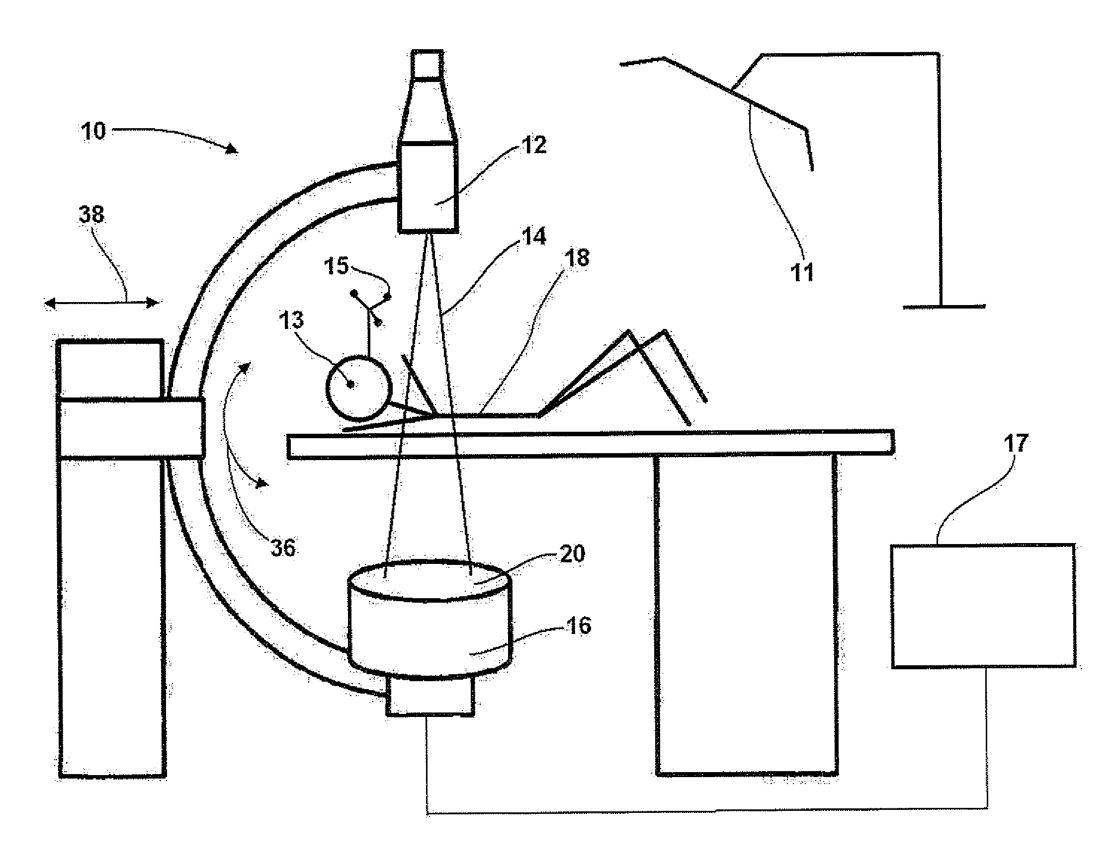
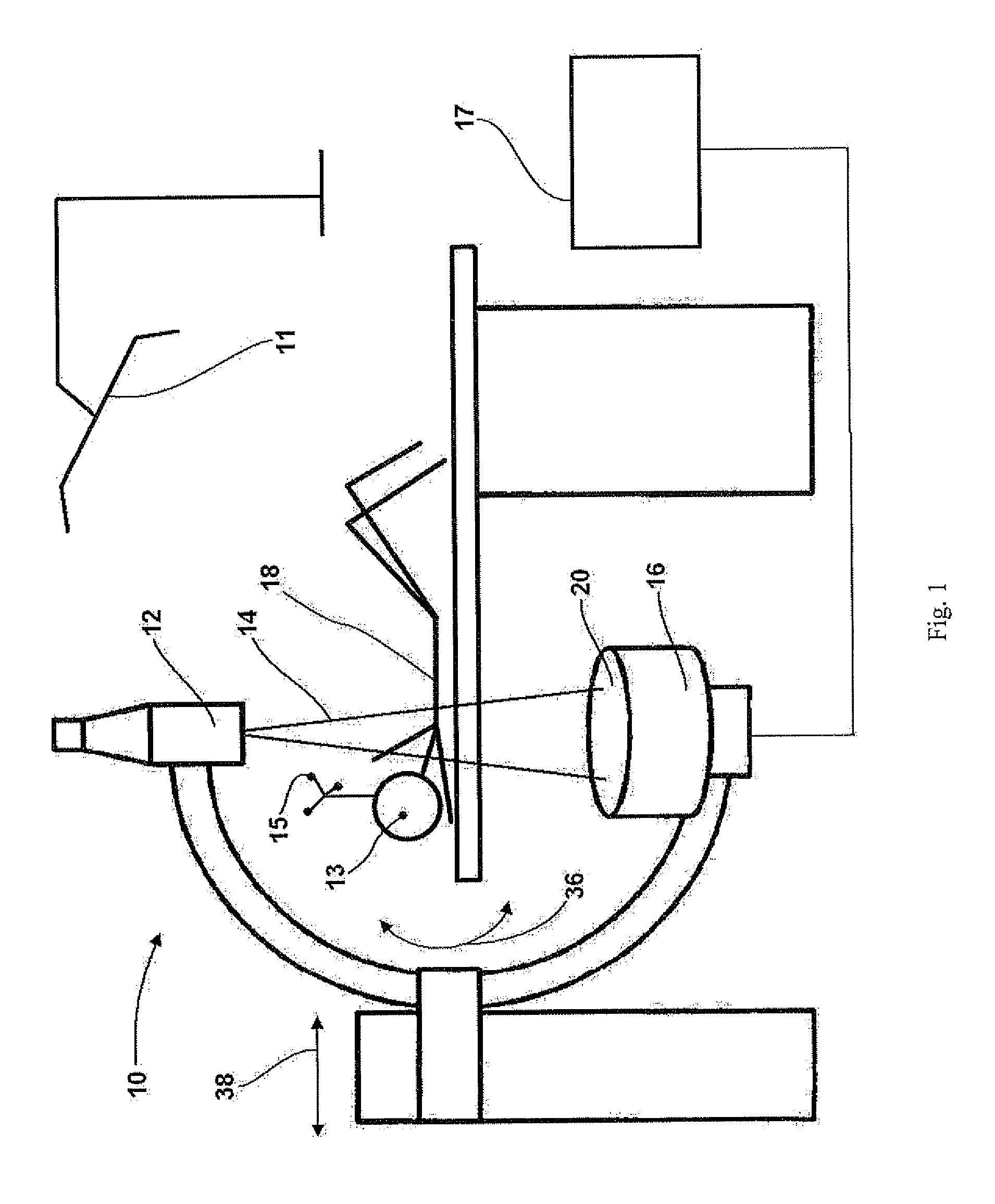
[0103]In FIG. 1, the method of determining an imaging direction of an imaging apparatus 10, such as a C-arc, with reference to an object 18, is shown. The imaging apparatus 10 comprises an imaging source 12 that emits an imaging beam 14 to an imaging detector 16 in the beam path. The image detector 16 has a plane detecting surface, which is comprised by or is part of an imaging plane 20. The imaging plane 20 is perpendicular to the imaging beam 14. The spatial positions of both imaging source 12 and imaging detector 16 are variable with reference to the object 18 by adapting the angle of the imaging beam 14 or the shift of the imaging beam 38.

[0104]The method comprises the steps of:[0105]imaging the object 18 from a first direction to obtain a first 2D image;[0106]providing 3D reference data, for example a generic or statistical 3D model or an earlier obt...


PUM


Abstract

The present invention relates to a method for determining an imaging direction of an imaging apparatus (10), such as an x-ray apparatus, with a radiation source or an imaging source (12) that emits an imaging beam (14) to an imaging detector (16) along a beam path, comprising the steps of imaging an object (18) from a first direction to obtain a first 2D image; providing 3D reference data, for example a generic or statistical 3D model or an earlier obtained 3D data set, of the imaged object (18); performing a 2D/3D matching of the first 2D image with the 3D reference data to determine a position of an imaging plane (20, 22, 24) of the first 2D image relative to the 3D reference data; and determining the imaging direction of the imaging apparatus (10) relative to the object (18) based on the position of the imaging plane (20, 22, 24) relative to the 3D reference data, as well as to a navigation system for computer-assisted surgery comprising the imaging system of the preceding claim; a tracking system (11), such as optical or IR tracking means; detection devices (13, 15) such as e.g. radiopaque markers (13) detectable by the imaging system and markers (15) detectable by the tracking system (11) attachable to an object (18), wherein the navigation system is adapted to detect a position of the object (18) based on the detection devices (13, 15), in order to generate detection signals and to supply the detection signals to the computer (17) such that the computer can determine point data on the basis of the detection signals received; a calibration object such as a patient body or a phantom bearing detection devices for calibrating the navigation system.

Description

FIELD OF THE INVENTION[0001]The present invention relates to a method for determining an imaging direction of an imaging apparatus, such as an x-ray apparatus, to a method for calibrating a 2D imaging apparatus, to a related program, program storage medium, imaging system and navigation system.BACKGROUND OF THE INVENTION[0002]In medical imaging, correct representation of imaged tissue structures is of substantial importance for efficient diagnostics or surgical interventions on the basis of the obtained images. Thus, efforts are currently made to correct misrepresentations of the imaged structures, wherein the prevalent medical imaging systems are Ultrasonography, X-ray such as e.g. Fluoroscopy or Computed Tomography, and Magnetic Resonance Imaging.[0003]Some methods for correcting misrepresentations of imaged structures account for deviations of the projection geometry from the actual geometry of the imaging system. For example, mechanical flexure of an X-ray diagnostic machine e.g...

Claims


Application Information

Patent Timeline
IPC IPC(8): G06T7/00
CPCA61B6/4441G06T7/0014A61B19/5244A61B2017/00707A61B2017/00725A61B2019/5238A61B2019/5255A61B2019/5289G06T7/0018G06T7/0046G06T2207/10072G06T2207/10121G06T2207/10124G06T2207/30004G06T2207/30244A61B6/584A61B2034/2055A61B34/20A61B2090/364A61B2090/376G06T7/80G06T7/75
Inventor FEILKAS, THOMAS
Owner BRAINLAB
Why Eureka
Try Eureka