
Method and apparatus for correction of artifacts in magnetic resonance images

a magnetic resonance and artifact correction technology, applied in the field of artifact correction of magnetic resonance images, can solve the problems of blurred artifacts at the image edge, no longer excited outer image regions, and artifact-plagued mr images, and achieve the effect of reducing artifacts in mr measuremen

Active Publication Date: 2013-04-25
SIEMENS HEALTHCARE GMBH
View PDF5 Cites 14 Cited by
  • Summary
  • Abstract
  • Description
  • Claims
  • Application Information

AI Technical Summary

Benefits of technology

This patent is about a way to improve magnetic resonance imaging (MRI) by reducing interference caused by changes in the magnetic field during the MRI process. The method uses a perturbation matrix to show how the magnetic field and gradients affect the image quality. By inverting this matrix, the MRI system can correct for any non-uniform excitation and create better quality images. The method also allows for stronger gradients and longer excitation pulses without compromising image quality. Overall, this method improves the accuracy and quality of MRI without limiting the flexibility of MRI technology.

Problems solved by technology

In the case of insufficient pulse bandwidth or gradients that are too strong, it may be that the outer image regions are no longer sufficiently excited.
In the reconstructed MR image, this incorrect excitation has the effect of blurring artifacts at the image edge, which are pronounced more strongly the stronger the gradients switched during the excitation.
An insufficient excitation thus leads to artifact-plagued MR images.
This procedure therefore also cannot be used without limitations and is accompanied by a degradation of the image quality.

Method used


Image

  • Method and apparatus for correction of artifacts in magnetic resonance images
  • Method and apparatus for correction of artifacts in magnetic resonance images
  • Method and apparatus for correction of artifacts in magnetic resonance images

Examples


Embodiment Construction

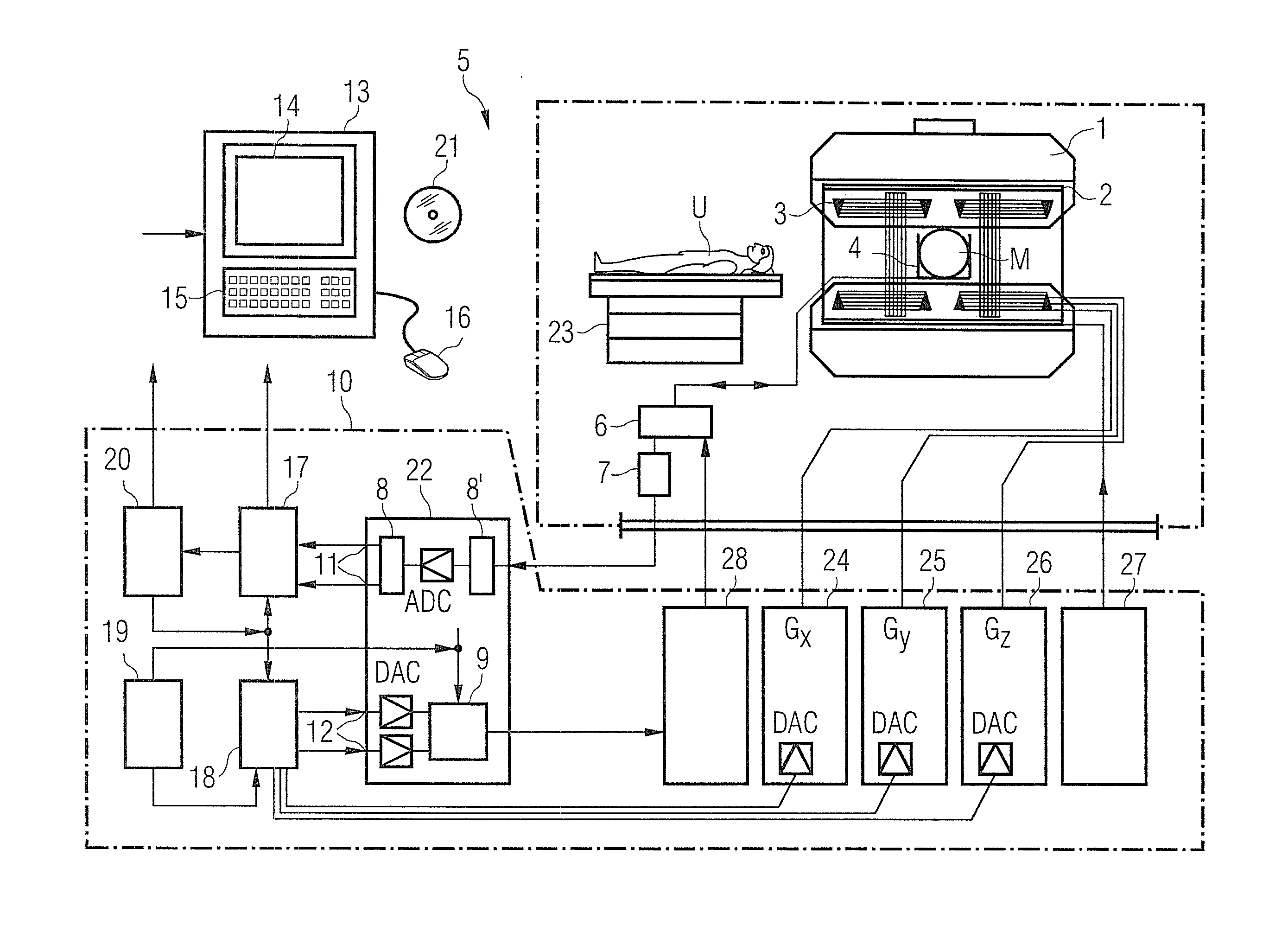
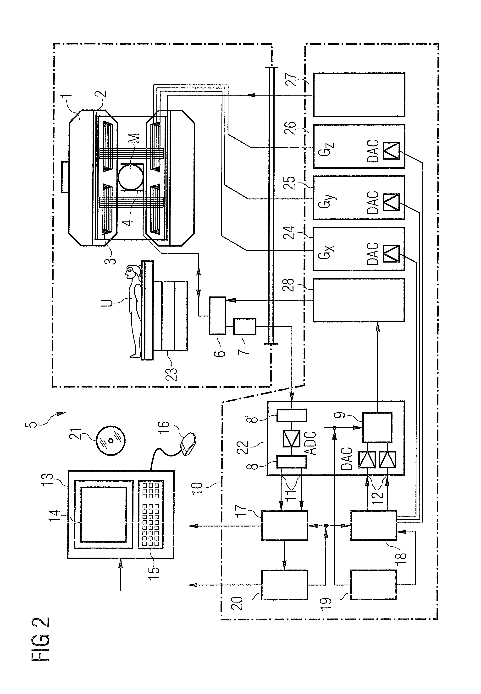
[0033]FIG. 2 schematically illustrates a magnetic resonance system 5 (a magnetic resonance imaging or magnetic resonance tomography apparatus). A basic field magnet 1 generates a temporally constant, strong magnetic field for polarization or alignment of the nuclear spins in an examination region of an examination subject U, for example of a part of a human body that is to be examined, which part lies on a table 23 and is moved into the magnetic resonance system 5. The high homogeneity of the basic magnetic field that is required for the magnetic resonance measurement is defined in a typically spherical measurement volume M into which the parts of the human body that are to be examined are introduced. To support the homogeneity requirements, and in particular to eliminate temporally variable influences, shim plates made of ferromagnetic material are mounted at a suitable point. Temporally variable influences are eliminated via shim coils 2 and a suitable controller 27 for the shim c...


PUM


Abstract

In a method and apparatus for the correction of artifacts in magnetic resonance images (MR) acquired with an MR pulse sequence in which gradients are switched simultaneously during the radiation of at least one non-selective excitation pulse, measurement data acquired with the pulse sequence in k-space are loaded into a processor, in which a perturbation matrix is determined on the basis of spatial and k-space point data of the acquired measurement data and the gradients used during the excitation. A corrected image is calculated from the acquired measurement data in k-space and the perturbation matrix, with the calculation of the corrected image including a matrix inversion of the perturbation matrix. The corrected image is then stored or displayed.

Description

BACKGROUND OF THE INVENTION[0001]1. Field of the Invention[0002]The invention concerns: a method to correct artifacts in magnetic resonance (MR) images by means of an MR pulse sequence in which gradients are switched (activated) simultaneously during the radiation of at least one excitation pulse, as well as a magnetic resonance apparatus and an electronically readable data medium for implementing such a method.[0003]2. Description of the Prior Art[0004]The magnetic resonance modality (also known as magnetic resonance tomography) is a known technique with which images of the inside of an examination subject can be generated. Expressed simply, for this purpose the examination subject is positioned within a strong, static, homogeneous basic magnetic field (also called a B0 field) having a field strength of 0.2 Tesla to 7 Tesla and more, such that the nuclear spins of the examination subject are oriented along the basic magnetic field. To trigger nuclear magnetic resonance signals, rad...

Claims


Application Information

Patent Timeline
IPC IPC(8): G06K9/00
CPCA61B5/7203A61B5/055G01R33/4816G01R33/565A61K48/00G01R33/48G06F17/16
Inventor GRODZKI, DAVIDHEISMANN, BJOERN
Owner SIEMENS HEALTHCARE GMBH
Learn More