High pressure molding of composite parts

a technology of composite parts and molding chambers, which is applied in the direction of machines/engines, stators, liquid fuel engines, etc., can solve the problems that the mandrel material cannot be melted and removed from the airfoil chamber without damaging the resin matrix, so as to prevent the distortion of the mandrel material and reduce the weight of the vane

Active Publication Date: 2013-04-25
HEXCEL
View PDF2 Cites 65 Cited by
  • Summary
  • Abstract
  • Description
  • Claims
  • Application Information

AI Technical Summary

Benefits of technology

[0012]As another feature of the invention, composite outlet guide vanes are provided where the weight of the vane is reduced by forming a hollow chamber inside of the central airfoil portion. The hollow outlet guide vane is made by molding a pre-form that has a shape which closely matches the shape of the outlet guide vane. The pre-form or moldable body is composed of fiber reinforcement and uncured thermosetting resin. The uncured thermosetting resin has a curing temperature at which the resin is converted from a moldable resin to a solid resin having a glass transition temperature (Tg) that is well-above the curing temperature. A solid mandrel is located within the pre-form so as to form a chamber inside of the central airfoil portion. The solid mandrel is composed of a material that melts to form a liquid at a melting temperature that is above the curing temperature of the thermosetting resin, but below the glass transition temperature of the cured solid resin. It was discovered that solid mandrels that melt above the curing temperature are required for high pressure molding of combined composites to prevent distortion of the mandrel material and seepage of liquid mandrel material at the high pressures required to provide suitable composite parts. The mandrel material must also melt below the glass transition temperature of the cured part. Otherwise, the mandrel material cannot be melted and removed from the airfoil chamber without damaging the resin matrix of the part.

Problems solved by technology

Otherwise, the mandrel material cannot be melted and removed from the airfoil chamber without damaging the resin matrix of the part.

Method used


Image

  • High pressure molding of composite parts
  • High pressure molding of composite parts
  • High pressure molding of composite parts

Examples


example 1

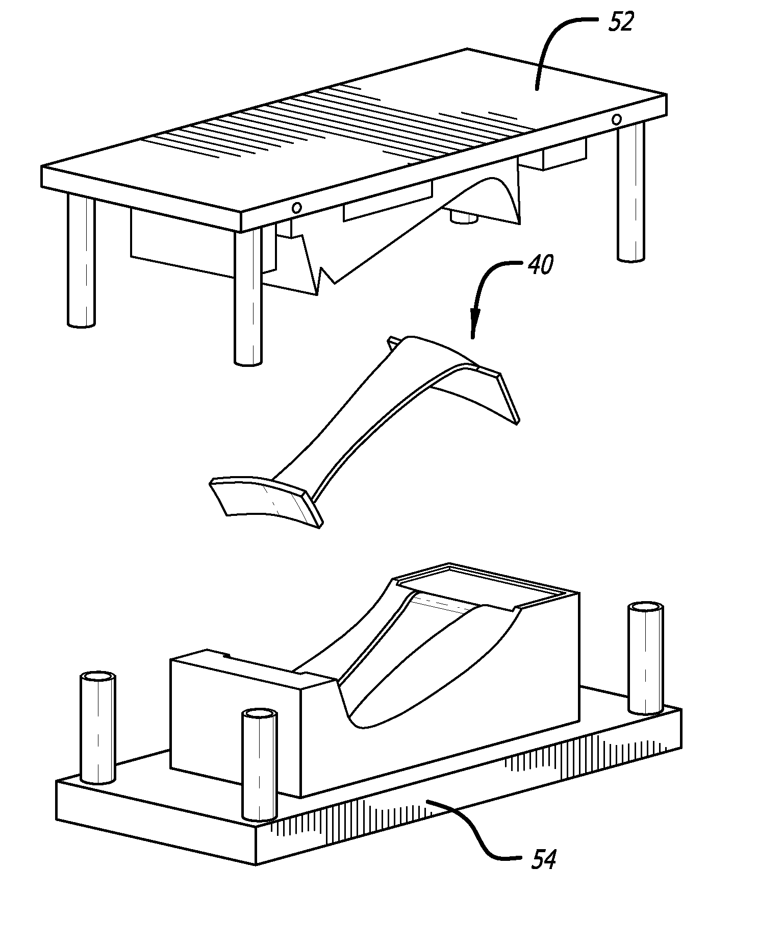
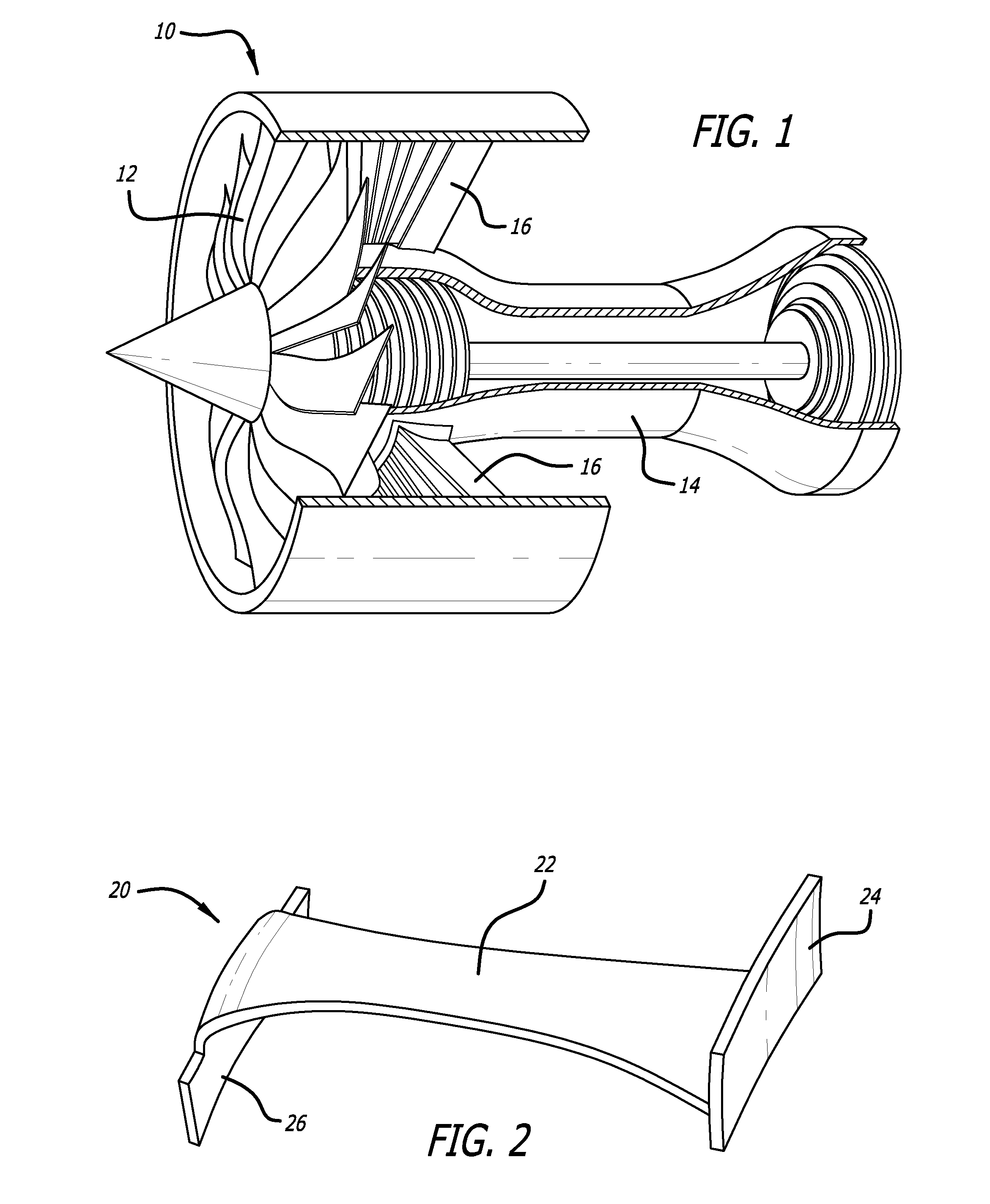
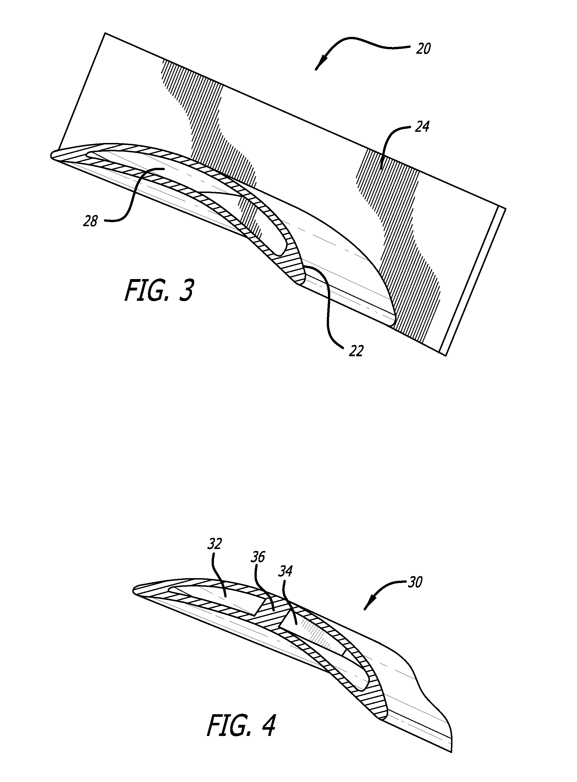
[0049]A pre-form of the type shown at 40 in FIG. 8 was prepared in order to produce an outlet guide vane of the type shown at 20 in FIGS. 2 and 3. The outlet guide vane had an airfoil portion that was 9 inches tall and ranged in width from 2 inches to 4 inches. The thickness of the airfoil ranged from 0.040 inch to 0.250 inch. The flanges were each about 5 inches wide, 2 inches long and 0.230 inch thick. A mandrel of the type shown at 50 in FIG. 7 was prepared from a eutectic metal alloy composed of 91 weight percent tin and 9 weight percent zinc (melting point—199° C.). The airfoil portion of the pre-form was prepared by covering the mandrel with AS4 / 8552HexPly® unidirectional tape prepreg that had a resin content of 38 weight percent. The UD tape was laid so that it extended longitudinally between the flanges or platforms and overlapped into the flanges by about 1.5 inch. The flange portions of the pre-form were made from AS4 / 8552 HexMC® that had a resin content of 38 weight perce...

example 2

[0051]An outlet guide vane is prepared in the same manner as Example 1, except that the entire pre-form is made from AS4 / 8552 HexMC® that has a resin content of 38 weight percent. The pre-form is staged and cured in the same manner as Example 1. The eutectic metal mandrel is melted and removed as in Example 1 and the part is cooled to provide an all composite chambered outlet guide vane. This all composite part can be machined in all areas to meet design and dimensional tolerances. The part is also expected to be equal to comparative metal outlet guide vanes in compressive strength, resistance to buckling, fatigue resistance and natural frequency in the free-state condition.

example 3

[0052]A solid outlet guide vane of the type shown at 60 in FIG. 6 was made in the same manner as Example 1, except that the mandrel was eliminated and AS4 / 8552HexPly® unidirectional tape prepreg was used instead to provide a solid airfoil portion that was composed entirely of unidirectional fibers. In addition, the leading edge of the pre-form was covered with a protective sheet of 316 stainless steel that was 0.004 inch thick. A thin layer of BEMIS 4220 polyamide adhesive was located between the protective sheet and the leading edge of the composite pre-form. The pre-form was molded in the same manner as Example 1, except that the extra heating step to remove the fusible mandrel was not required. The resulting solid outlet guide vane was also found to be better than comparative metal outlet guide vanes in compressive strength and resistance to buckling. Although the hollow and solid outlet guide vanes have the same geometry, they can be used to meet different structural requirement...


PUM

PropertyMeasurementUnit
temperatureaaaaaaaaaa
pressureaaaaaaaaaa

Abstract

Composite pre-forms are molded at high pressure to form composite parts that can be used in place of metal-based high performance parts, such as the outlet guide vanes found in turbofan jet engines. The composite pre-forms include two different fiber orientations that are co-molded in a resin matrix at high pressures to provide composite outlet guide vanes and other high performance parts. Chambers within the composite part are optionally formed during molding of the pre-form at high pressures.

Description

BACKGROUND OF THE INVENTION[0001]1. Field of the Invention[0002]The present invention relates generally to the molding of pre-formed fiber-reinforced resin components into composite parts that have multiple fiber orientations and / or one or more internal chambers. More particularly, the present invention is directed to molding of such pre-forms under high pressure.[0003]2. Description of Related Art[0004]Composite materials typically include fibers and a resin matrix as the two principal components. Composite materials typically have a rather high strength to weight ratio. As a result, composite materials are being used in demanding environments, such as in the field of aerospace where the high strength and relatively light weight of composite parts are of particular importance.[0005]High strength metals and metal alloys have been used in the past to form aircraft parts and structures that are subjected to high stress loads. An advantage of using metal is that, in addition to being e...

Claims


Application Information

Patent Timeline
Patent Type & Authority Applications(United States)
IPC IPC(8): F01D9/02B32B5/12B32B27/18
CPCB29C70/46B29C33/52B29D99/0028B29C70/081Y10T29/49867Y10T428/1352Y10T428/24124Y10T29/49799B29L2031/08
Inventor KWEDER, MATTHEWBOURSIER, BRUNO
Owner HEXCEL
Why Eureka
Try Eureka