Method for encapsulating semiconductor and structure thereof
a technology of encapsulating and semiconductors, applied in semiconductor/solid-state device details, thin material processing, semiconductor devices, etc., can solve the problems of substrates still suffering inevitable distortion and insufficient support plane space, so as to increase the component layout density and reduce the overall thickness of the substrate.
- Summary
- Abstract
- Description
- Claims
- Application Information
AI Technical Summary
Benefits of technology
Problems solved by technology
Method used
Image
Examples
embodiment 1
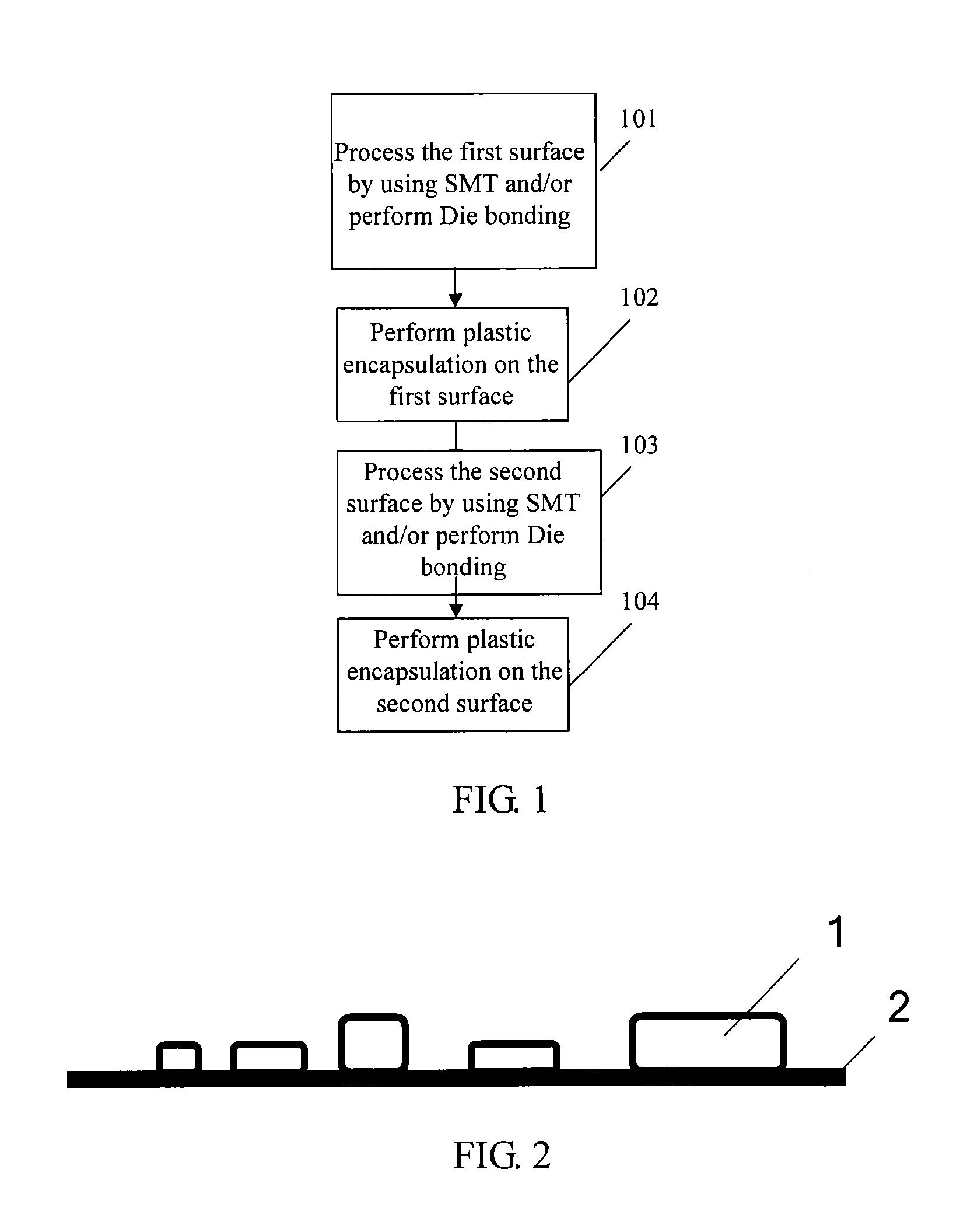
[0026]As shown in FIG. 1, a method for encapsulating a component with plastic includes the following steps:
[0027]Step 101: Process, by using the SMT (Surface-mount Technology, surface mounting technology), a first surface and / or performing Die bonding (die bonding) on the first surface: Process, by using the surface mounting technology, the first surface of a part to be encapsulated with plastic and / or performing die bonding on the first surface.
[0028]Step 102: Encapsulate the first surface with plastic: Encapsulate, with plastic, the first surface of the part to be encapsulated with plastic which has undergone the processing performed by using the surface mounting technology and / or has undergone the die bonding.
[0029]Step 103: Process a second surface by using the SMT and / or performing Die bonding (die bonding) on the second surface: Process, by using the SMT, the second surface of the part to be encapsulated with plastic the first surface of which has undergone the encapsulating w...
embodiment 2
[0032]As shown in FIG. 1, a method for encapsulating a component with plastic includes the following steps:
[0033]Step 101: As shown in FIG. 2, process a first surface by using the SMT: Complete work procedures for a single surface, such as solder paste printing, pasting, and reflow, so that a component 1 is fixed on the front surface of a substrate 2; or perform Die bonding.
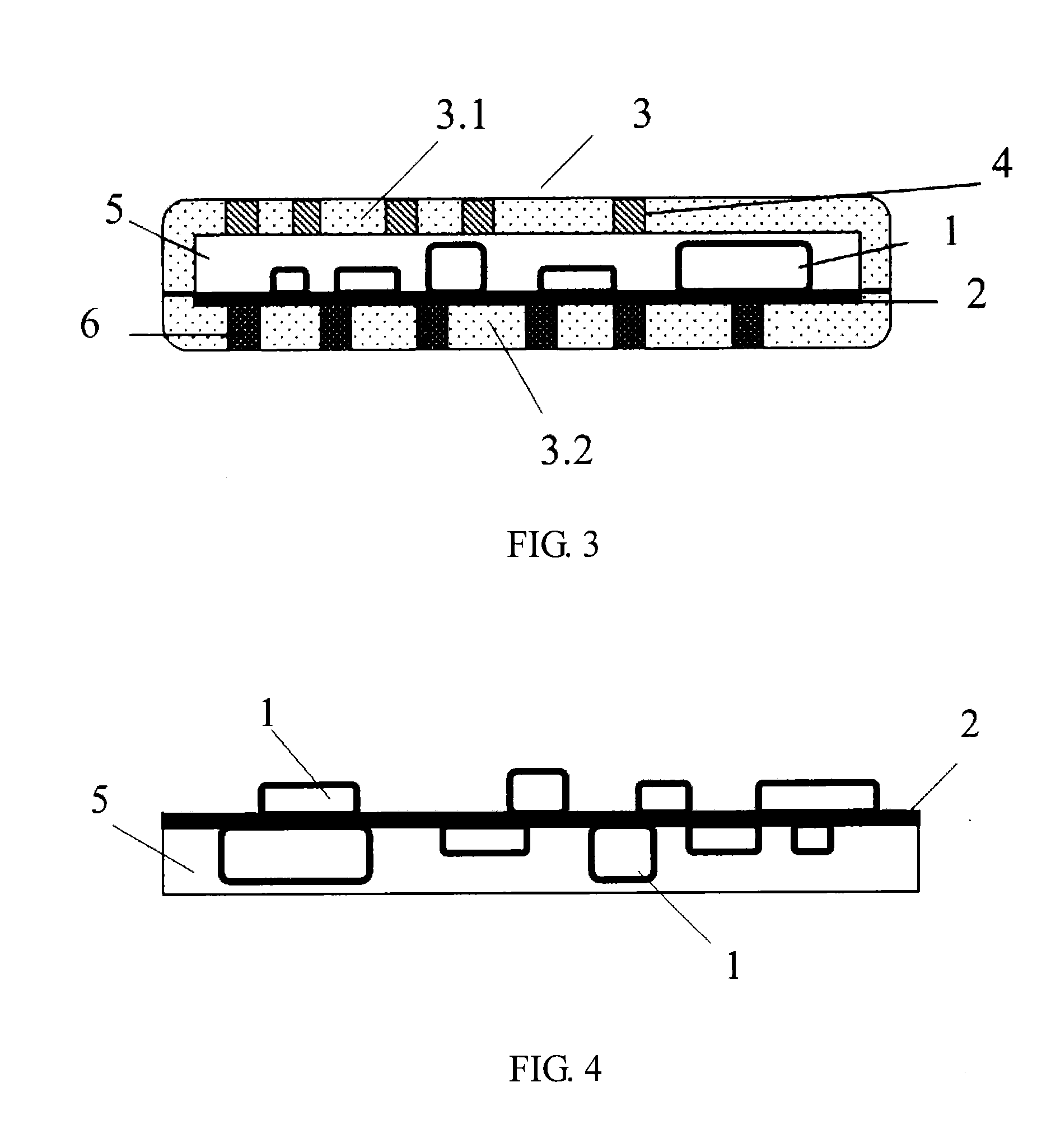
[0034]Step 102: As shown in FIG. 3, encapsulate the first surface with plastic: Place a part to be encapsulated with plastic the first surface of which is processed in a mould cavity of a mold 3; combine an upper mold 3.1 and a lower mold 3.2; vacuum the bottom of the substrate 2 through a vacuum suction hole 6 at the bottom of the lower mold 3.2; inject glue through a glue injection hole 4; perform solidation so that the component 1 on the substrate 2 is encapsulated with plastic by using a seal 5.
[0035]Step 103: As shown in FIG. 4, process a second surface with SMT: Complete work procedures for a second surface...
embodiment 3
[0038]As shown in FIG. 7, this embodiment is based on Embodiment 2, and changes the manner by using which a second surface is encapsulated with plastic into a dispensing manner in which molds are not used to inject plastic. Mould opening is not required in the operation, which has the advantage of easy operation.
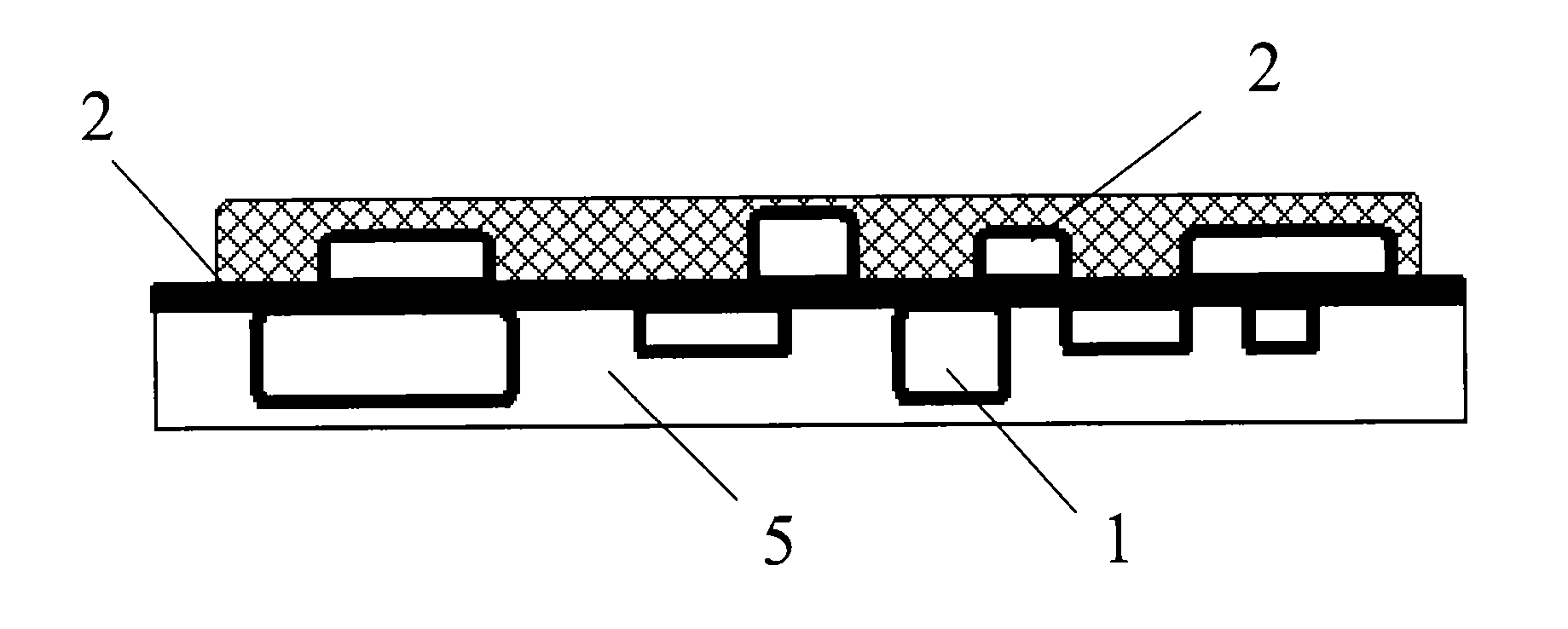
[0039]FIG. 6 shows an encapsulation structure for encapsulating a component with plastic, including a substrate 2, where components 1 are fixed on both an upper surface and a lower surface of the substrate 2, and the components 1 on the upper surface and lower surface are both encapsulated with plastic in a seal 5.
[0040]The dual-surface plastic encapsulation of the component in this embodiment endows both surfaces with characteristics such as dustproof and waterproof, and good internal sealability.
[0041]As shown in FIG. 8, the upper surface and / or lower surface of the seal 5 are in a step-like form. Preferably, one surface of the seal 5 is in the step-like form.
[0042]When th...
PUM
 Abstract
Description
Claims
Application Information
 - R&D
- Intellectual Property
- Life Sciences
- Materials
- Tech Scout
- Unparalleled Data Quality
- Higher Quality Content
- 60% Fewer Hallucinations
Browse by: Latest US Patents, China's latest patents, Technical Efficacy Thesaurus, Application Domain, Technology Topic, Popular Technical Reports.
© 2025 PatSnap. All rights reserved.Legal|Privacy policy|Modern Slavery Act Transparency Statement|Sitemap|About US| Contact US: help@patsnap.com


