Pump for liquid chromatograph, and liquid chromatograph

Active Publication Date: 2013-05-02
HITACHI HIGH-TECH CORP
View PDF11 Cites 37 Cited by
  • Summary
  • Abstract
  • Description
  • Claims
  • Application Information

AI Technical Summary

Benefits of technology

[0012]The present invention can provide a pump for liquid chromatograph, and a liquid chroma

Problems solved by technology

However, the inventions described in Patent Document 1 and Patent Document 2 do not take into consideration the processing accuracy, assembly accuracy, and control accuracy of the pumps.
For example, a cyclic pulsation occasionally occurs due to a backlash or a dimensional looseness in a cam mechanism for driving a plunger pump, man

Method used


Image

  • Pump for liquid chromatograph, and liquid chromatograph
  • Pump for liquid chromatograph, and liquid chromatograph
  • Pump for liquid chromatograph, and liquid chromatograph

Examples


embodiment

[0026]First of all, a configuration of the present invention is summarized as follows.

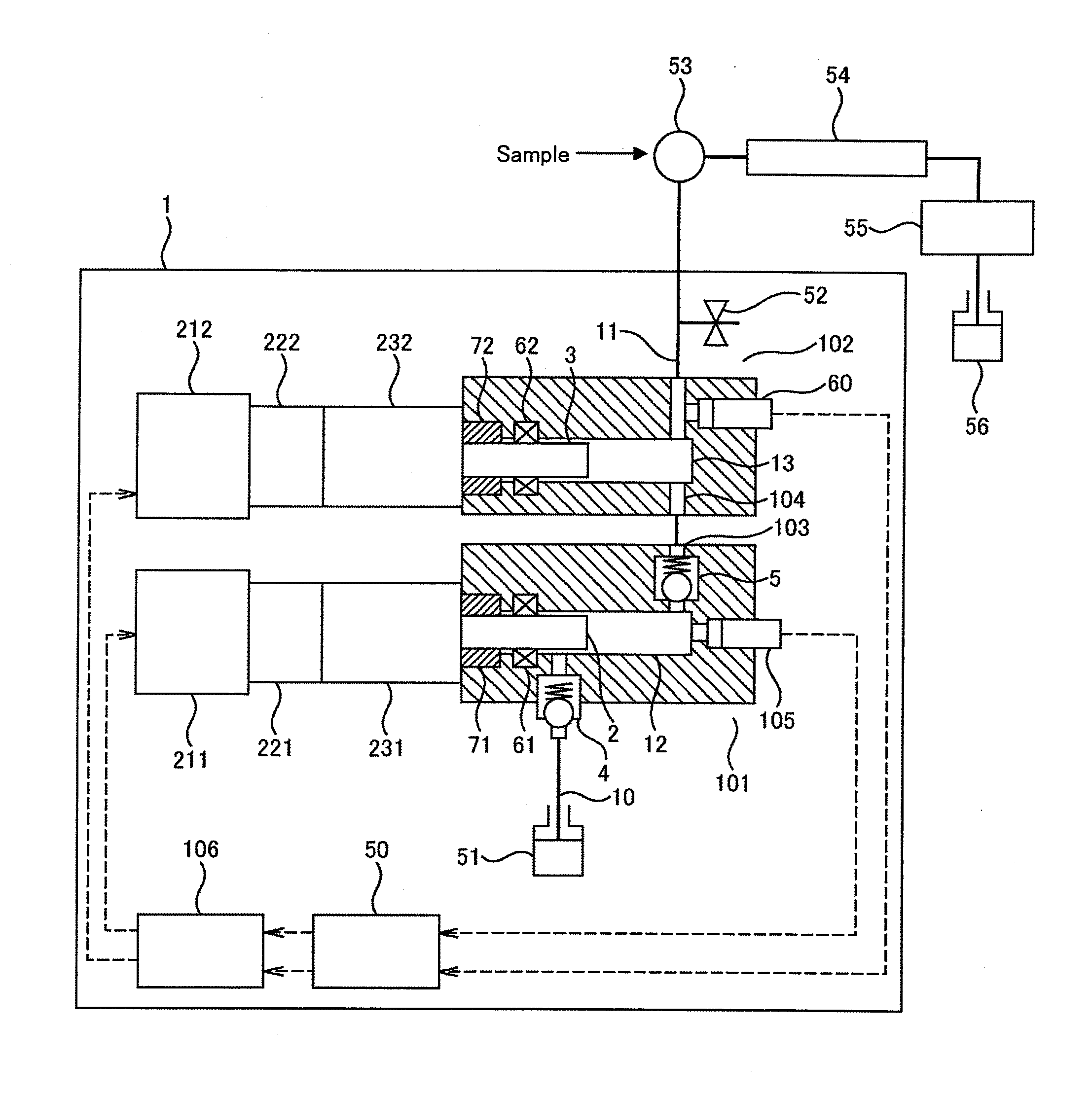
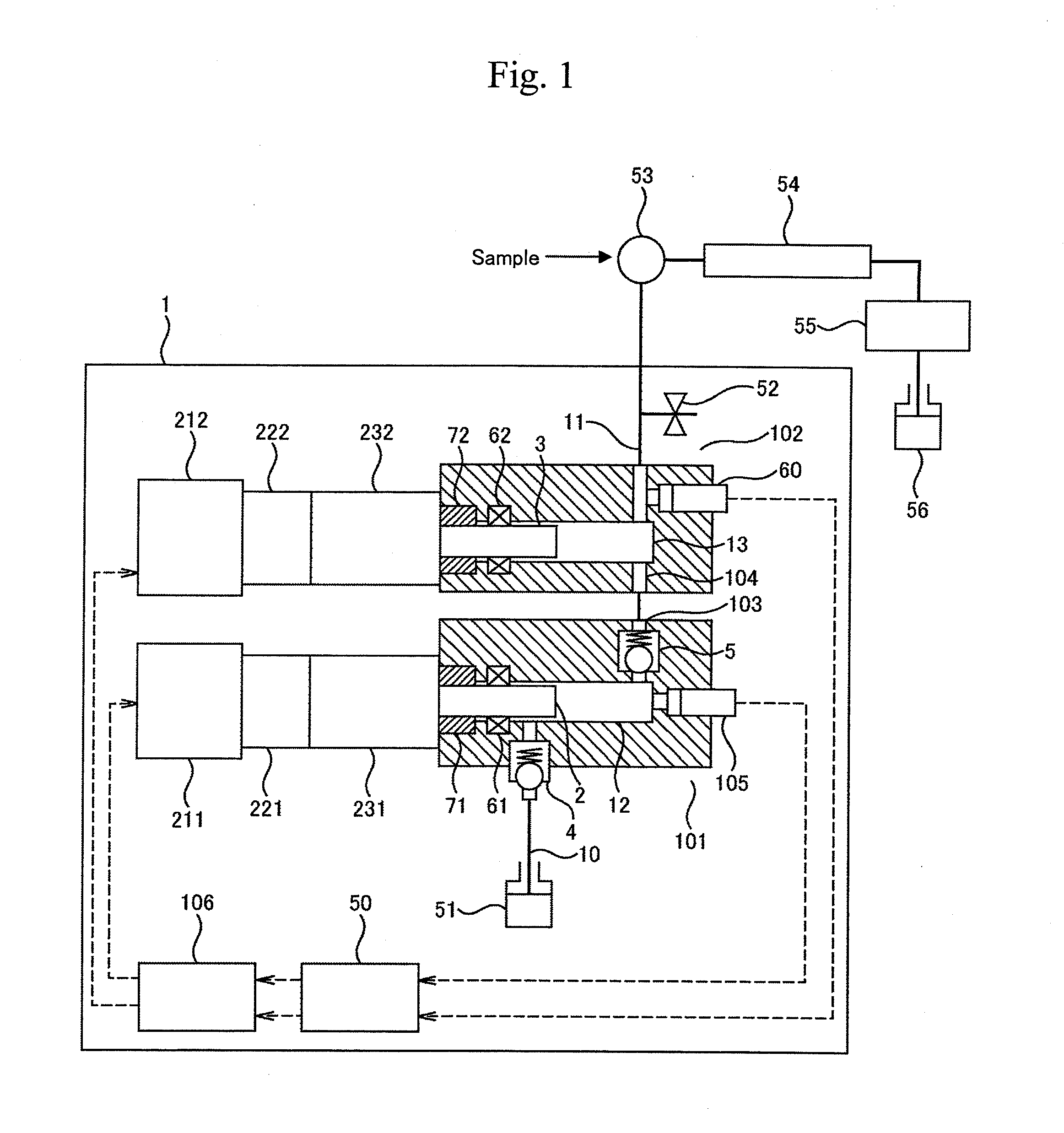
[0027]A pump for liquid chromatograph according to the present invention includes a first plunger pump and a second plunger pump connected in series or in parallel, a first plunger configured to reciprocate inside a pressurizing chamber of the first plunger pump, a second plunger configured to reciprocate inside a pressurizing chamber of the second plunger pump, at least one electric motor configured to generate rotative power, a power transmission mechanism configured to convert the rotative power of the electric motor into linear reciprocating power and to provide the first plunger and the second plunger with drive power, a motor driver configured to control the electric motor, a first pressure sensor provided in the pressurizing chamber of the first plunger pump, a second pressure sensor provided in a channel on a downstream side of the second plunger, and a pump controller configured to read me...


PUM


Abstract

A pump controller causes a first plunger pump and a second plunger pump connected in series or in parallel to perform intake and compression actions alternately at substantially constant cycles, sets a pressurizing chamber of one of the plunger pumps to a state of a higher pressure than the pressurizing chamber of the other plunger pump, and performs flow rate control by adjusting lift amounts of the first plunger and the second plunger. Thus, it is possible to provide a pump for liquid chromatograph, and a liquid chromatograph, which are capable of reducing pulsations even when an ejection flow rate is changed.

Description

TECHNICAL FIELD[0001]The present invention relates to a pump for liquid chromatograph, and a liquid chromatograph.BACKGROUND ART[0002]A conventionally known pump structure used in a liquid chromatograph includes two plunger pumps which are connected in series or in parallel in such a manner that a first plunger pump and a second plunger pump perform coordinated operations to reduce pulsations (see Patent Document 1, for example). The configuration disclosed in Patent Document 1, for instance, is the configuration in which the first plunger pump and the second plunger pump are connected in series and reciprocating motions of the plungers are driven by use of cams. In phase 1 of a pumping operation, a downstream pump 1a performs an intake action (at an ejection flow rate of 0) while an upstream pump 1b performs ejection at a flow rate of Q, and a total ejection amount is therefore equal to Q. In phase 2, both of the pumps perform ejection at a flow rate of Q / 2, and the total ejection ...

Claims


Application Information

Patent Timeline
IPC IPC(8): F04B17/03G01N30/02
CPCF04B13/00F04B23/06F04B49/065F04B2203/0202F04B2205/03G01N30/32F04B2205/05F04B17/03G01N30/02G01N30/34F04B49/06F04B49/08G01N2030/326
Inventor TOKUO, KENICHIROHIRAKU, KENJIKAJI, HIRONORIAKIEDA, DAISUKEISHII, KIMIHIKOYASUHARA, NAOYA
Owner HITACHI HIGH-TECH CORP
Why Eureka
Try Eureka