
High Efficiency LED Lighting System with Thermal Diffusion

Inactive Publication Date: 2013-05-02
OPTALITE TECH
View PDF6 Cites 27 Cited by
  • Summary
  • Abstract
  • Description
  • Claims
  • Application Information

AI Technical Summary

Benefits of technology

The present invention is an improved circuit design for an LED lighting system that operates without needing to connect to LED drivers. The design was created to reduce the flickering and power usage of the LED lights.

Problems solved by technology

However, in such uses heat management becomes a very important issue, and heat buildup is one of the leading causes of early LED failure.
The issue often leads to LED lighting solutions that appear underpowered and do not create enough usable ambient light.
Current heat reduction systems are inadequate to dissipate proper amounts of the heat bi-product causing reduction of LED lifespan, premature failure, and loss of ambient light.
Another emerging downside is the fact that most LEDs are incompatible with dimmers.
While some LED lights can be used with line-voltage incandescent dimmers, but the dimmer and LED driver electronics are not always compatible.
It is thus not possible to guarantee that a given LED fixture will work with all dimmers.
One source of inefficiencies in the systems is due to the power conversion from alternating current to direct current that is generally associated with such systems.
In these systems there is some amount of phantom power loss, due to the DC converter trickling a small amount of power, even when the system is off.
Each of these prior art systems suffers from one or more of the following limitations, problems, or shortfalls: requiring the use of LED drivers which are bulky, expensive, create waste heat, lower efficiency, and increase complexity; lacking active cooling; lacking passive cooling; lacking efficient cooling systems; being susceptible to solar heating; lacking cooling on both sides of the LEDs; being heavy; being bulky; being expensive; being of limited scale and brightness; having low watt equivalence; suffering from excessive flicker; providing no control of the shape of the area lit; not being dimmable; requiring a warm-up time; and causing light pollution.

Method used


Image

  • High Efficiency LED Lighting System with Thermal Diffusion
  • High Efficiency LED Lighting System with Thermal Diffusion
  • High Efficiency LED Lighting System with Thermal Diffusion

Examples


Embodiment Construction

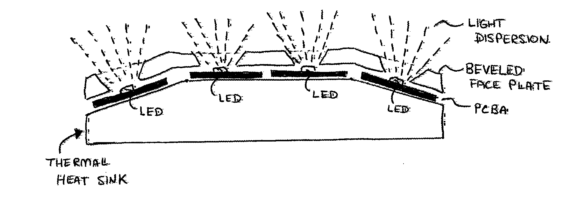
[0101]The present application presents an improved LED lighting system. The improved LED lighting system functions without LED drivers and offers improved efficiency and efficacy relative to the prior art. The system further comprises passive thermal diffusion structures, and optionally, active thermal diffusion means.

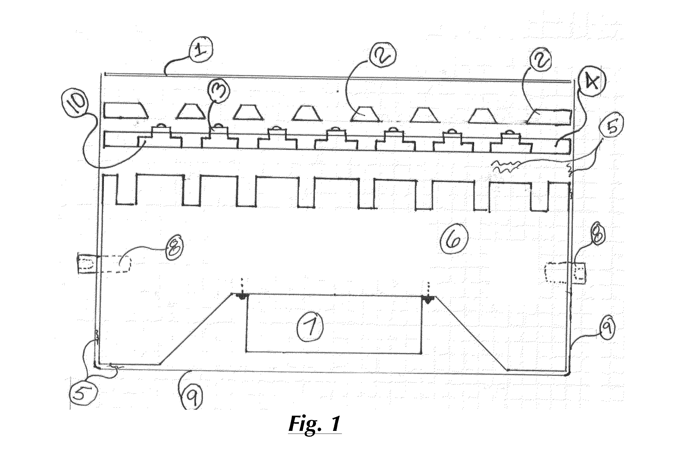
[0102]Turing first to FIG. 1, a cross-sectional diagrammatic side view of a preferred embodiment of the improved LED lighting system is shown. In this preferred embodiment the LED lighting system may be installed in a standard light fixture housing 9, such as but not limited to those in use indoors and outdoors, with some example outdoor uses including stadiums, flood lights, green house lights, and parking lot lights. The device preferably comprises a one-piece light guide faceplate coupled with a transformer, both housed within a housing having a rounded cover to provide protection from the elements when the device is used outdoors. The rounded cover is removable the...


PUM


Abstract

An apparatus including an LED lighting system for use within AC current and comprising a multi-phase circuit design providing an improved power delivery means which allows one half of the LEDs in the system to be lit during any given one half of the alternating current cycle and the other half to be lit during the other half of the current cycle. Further, a heat sink module comprising heat sink fins mates with custom LED footprints such that the module is mated to the footprints on at least ⅓ of its total surface area. Finally, the LED lighting apparatus and system comprises a faceplate comprising a beveled aperture through said faceplate directly above each LED, and wherein said bevel angle is at least zero and no more than 120 degrees.

Description

RELATED APPLICATIONS[0001]The present application claims priority from U.S. Provisional Patent Application 61 / 478,049, filed Apr. 21, 2012, which is incorporated by reference herein.BACKGROUND[0002]1. Field of the Invention[0003]The present invention relates in general to lighting technology and in particular to an LED-based lighting system designed to maximize energy efficiency and optimize thermal diffusion.[0004]2. Background of the Invention[0005]In recent years light systems based on light-emitting diodes (LED), a semiconductor light source, have become popular and widespread. Since becoming a practical source of light in the 1960s, LED based lights have moved to the mainstream and are now used in a wide variety of applications, ranging from LED headlamps, to LED replacement light bulbs, to LED based flood and streetlights. The efficiency and light output of LEDs has risen exponentially and they are now commonly understood to be a satisfactory light source for many applications...

Claims


Application Information

Patent Timeline
IPC IPC(8): F21V29/00F21V23/00H05B44/00
CPCF21V29/22F21V23/00F21S9/03F21V5/002F21V11/04F21V29/70F21Y2105/003F21Y2111/001F21Y2113/005A01G9/26F21V29/15H05B33/0803Y02B10/10F21Y2105/12F21Y2105/10F21Y2115/10F21Y2107/00F21Y2113/13A01G9/249H05B45/30H05B45/357
Inventor WYRICK, SAMMALONE, SEANLAUZON, BRIAN
Owner OPTALITE TECH
Learn More