Heat treatment apparatus

a technology of heat treatment apparatus and semiconductors, which is applied in the direction of welding apparatus, manufacturing tools, electric discharge tubes, etc., can solve the problems of extreme deterioration of thermal efficiency and energy efficiency required for heating, remarkable effects of thermal efficiency and high thermal efficiency

Active Publication Date: 2013-05-09
HITACHI HIGH-TECH CORP
View PDF26 Cites 36 Cited by
  • Summary
  • Abstract
  • Description
  • Claims
  • Application Information

AI Technical Summary

Benefits of technology

[0019]According to the present invention, thermal efficiency is hig

Problems solved by technology

When heating of 1200° C. or higher is performed in the resistance heating furnace disclosed in Japanese Patent Application Laid-Open Publication No. 2009-32774, problems described below become remarkable.
A first problem lies in thermal efficiency.
Since radiation is dominant as heat dissipation from a furnace body and a radiation amount is increased in proportion to biquadrate of the temperature, energy efficiency required for heating extremely deteriorates when a heating area is large.
Since a specimen to be heated gets away from a heat source (heater) by a double pipe, a heater unit needs to be at a higher temperature than the temperature of the specimen to be heated, also causing the efficiency to significantly deteriorate.
Due to the same reason as above, a heat capacity of a heated area becomes very large and it takes a time for the temperature to rise or drop.
A second prob

Method used


Image

  • Heat treatment apparatus
  • Heat treatment apparatus
  • Heat treatment apparatus

Examples


first embodiment

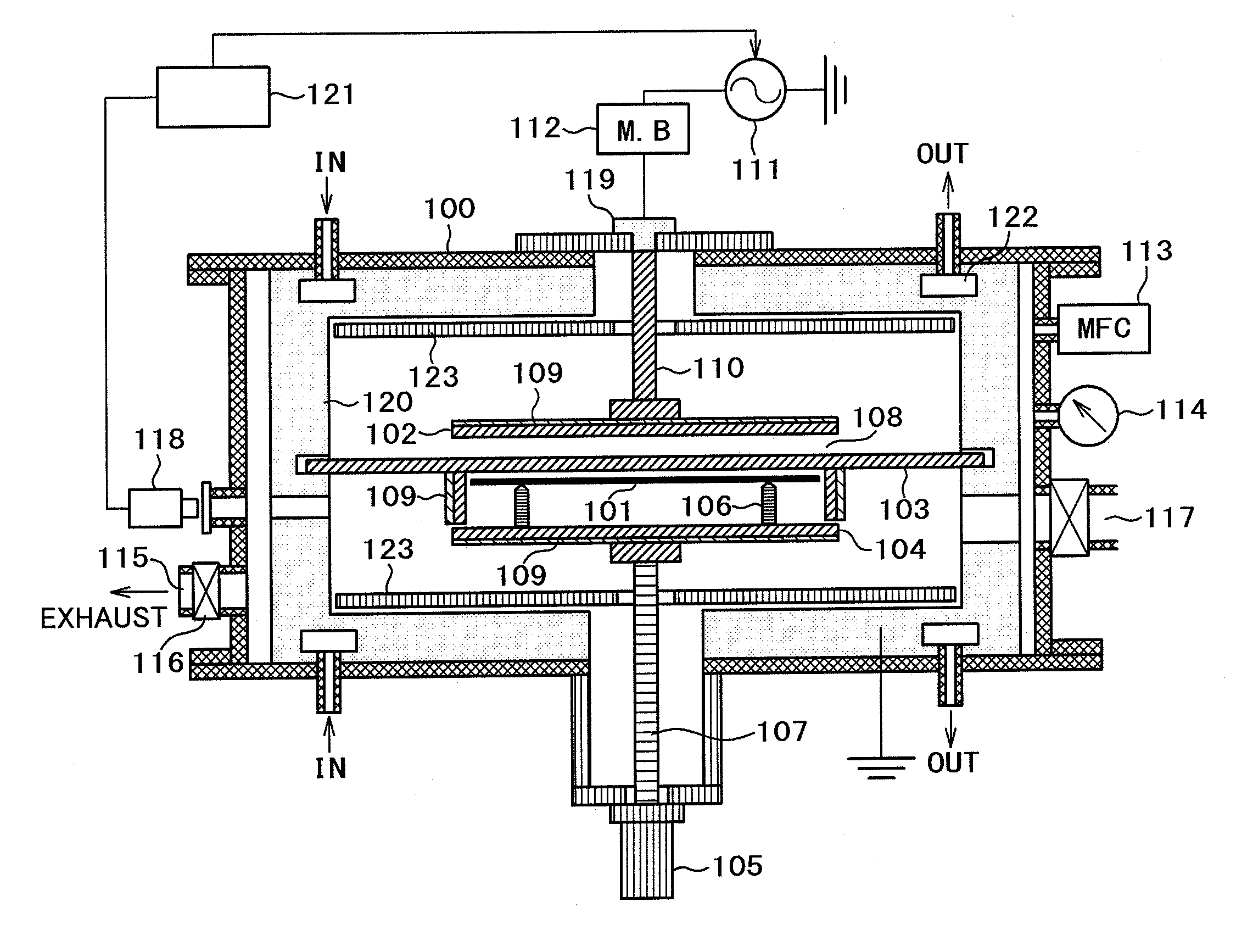
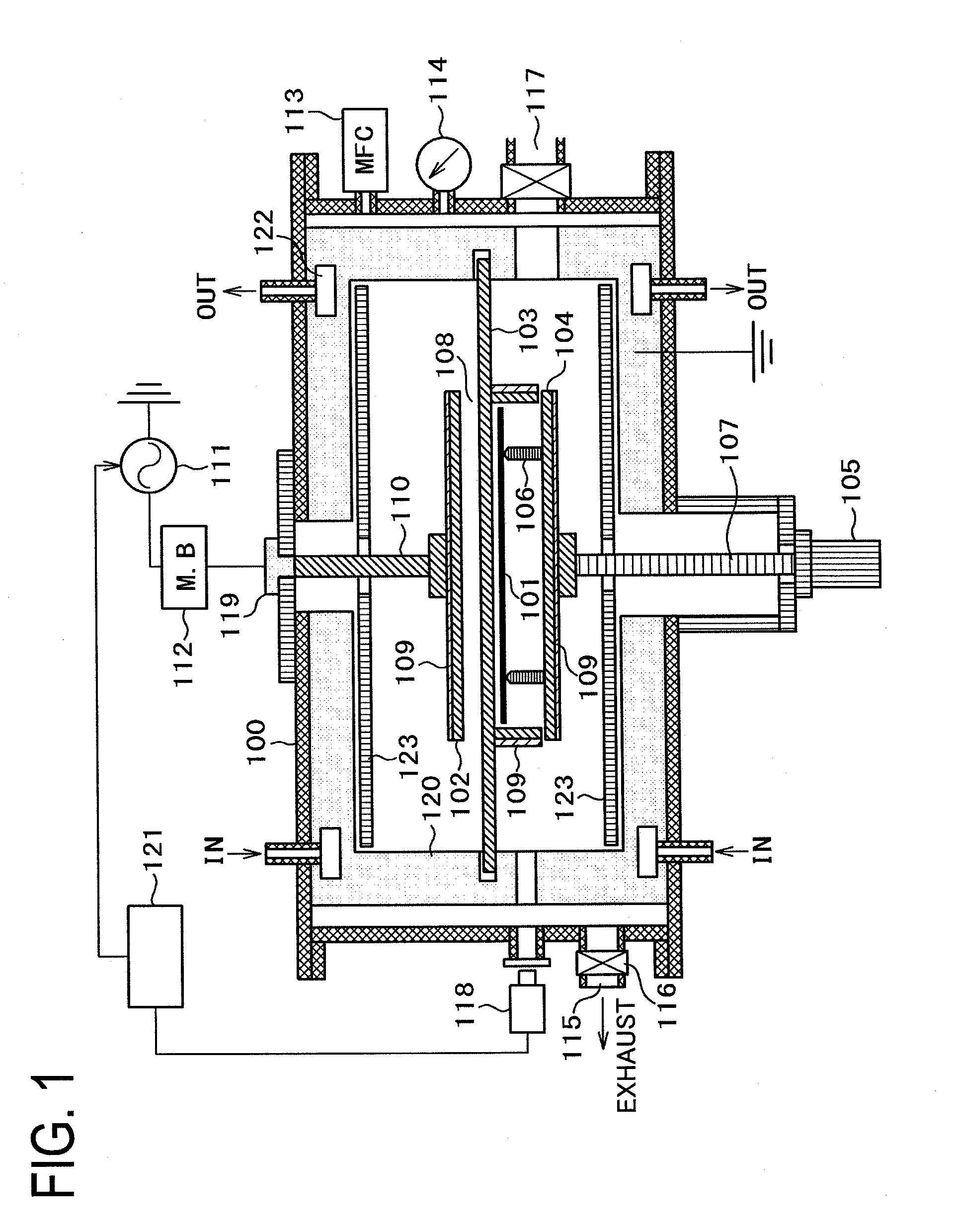
[0033]A basic configuration in a heat treatment apparatus according to the present invention will be described with reference to FIG. 1.

[0034]The heat treatment apparatus of the embodiment includes a heating treatment chamber 100 that heats a specimen 101 to be heated by using plasma.

[0035]The heating treatment chamber 100 includes an upper electrode 102, a lower electrode 103 opposed to the upper electrode 102 and serving as a heating plate, a specimen stage 104 having a support pin 106 supporting the specimen 101 to be heated, a reflection mirror (a first radiant heat suppressing member) 120 reflecting radiant heat, a radio-frequency power supply 111 supplying radio-frequency power for generating plasma to the upper electrode 102, a gas introduction means 113 supplying gas into the heating treatment chamber 100, and a vacuum valve 116 adjusting pressure in the heating treatment chamber 100.

[0036]The specimen 101 to be heated is supported on the support pin 106 of the specimen stag...

second embodiment

[0094]FIG. 5 is a diagram illustrating a basic configuration in which the preliminary heating chamber 200 is additionally placed to the heat treatment apparatus of the first embodiment.

[0095]The same reference numerals as those of the first embodiment refer to components serving to perform the same functions. Therefore, a description thereof will be omitted.

[0096]In the heat treatment apparatus of the embodiment, the preliminary heating chamber 200 is connected to the lower part of the heating treatment chamber 100 through a gate valve 202. Each of the heating treatment chamber 100 and the preliminary heating chamber 200 is airtightly closed by closing the gate valve 202. The heating treatment chamber 100 and the preliminary heating chamber 200 are in communication with each other by opening the gate valve 202.

[0097]The heat of the preliminary heating chamber 200 is exhausted by a vacuum pump (not illustrated) connected to an exhaust port 203 and a vacuum valve 204.

[0098]The specime...

third embodiment

[0102]A basic configuration of a heat treatment apparatus according to a third embodiment will be described with reference to FIG. 6.

[0103]The heat treatment apparatus of the embodiment includes a heating treatment chamber 300 that heats a specimen 301 to be heated by using plasma.

[0104]The heating treatment chamber 300 includes an upper electrode 303 serving as the heating plate, which is mounted with the specimen 301 to be heated on the top thereof, a lower electrode 302 opposed to the upper electrode 303, a reflection mirror (a first radiant heat suppressing member) 308 reflecting radiant heat, a radio-frequency power supply 311 supplying radio-frequency power for generating plasma to the lower electrode 302, a gas introduction means 313 supplying gas into the heating treatment chamber 300, and a vacuum valve 316 adjusting pressure in the heating treatment chamber 300.

[0105]In the embodiment, as the specimen 301 to be heated, a 4 inch (φ100 mm) SiC substrate is used.

[0106]The dia...


PUM

PropertyMeasurementUnit
Thicknessaaaaaaaaaa
Poweraaaaaaaaaa
Melting pointaaaaaaaaaa

Abstract

Provided is a heat treatment apparatus that is high in thermal efficiency and can reduce surface roughness of a substrate to be treated even when a specimen is heated at 1200° C. or higher.
The heat treatment apparatus heating the specimen includes a heating plate heated by plasma formed in an area of a gap to heat the specimen.

Description

CLAIM OF PRIORITY[0001]This application is based upon and claims the benefit of priority from the prior Japanese Patent Application No. 2011-244083 filed on Nov. 8, 2011, Application No. 2012-092883 filed on Apr. 16, 2012, the entire contents of which are incorporated herein by reference.BACKGROUND OF THE INVENTION[0002]1. Field of the Invention[0003]The present invention relates to a semiconductor manufacturing apparatus for manufacturing a semiconductor device, and more particularly, to a heat treatment technology of performing activation annealing or repair annealing of defects and oxidation of the surface after doping of impurities performed in order to conductively control a semiconductor substrate.[0004]2. Description of the Related Art[0005]In recent years, introduction of a new material having a wideband gap such as silicon carbide (hereinafter, referred to as SiC) as a substrate material of a power semiconductor device has been expected. SiC which is a wideband gap semicond...

Claims


Application Information

Patent Timeline
IPC IPC(8): B23K9/00
CPCH01J37/32091H01L21/67115H01L21/324H01J37/32522H01L21/31
Inventor YOKOGAWA, KEN'ETSUMIYAKE, MASATOSHIUEMURA, TAKASHIIZAWA, MASARUSAKAI, SATOSHI
Owner HITACHI HIGH-TECH CORP
Why Eureka
Try Eureka