Leaf seal

Active Publication Date: 2013-05-16
ROLLS ROYCE PLC
View PDF5 Cites 3 Cited by
  • Summary
  • Abstract
  • Description
  • Claims
  • Application Information

AI Technical Summary

Benefits of technology

The patent describes a new design for seals that can reduce fatigue cracking and damp vibrations. The seals consist of leaves that are divided into blocks, which allows for more interference between the leaves and reduces the likelihood of cracking. The leaves also make face-to-face contact with their neighbors, which increases the dampening of vibrations. The spacing between the leaves in each block can be random or irregular to prevent resonance. The surfaces of the leaves can also be treated to adjust the amount of frictional damping. Overall, this design can improve the performance and lifespan of seals in various applications.

Problems solved by technology

By forming the leaves into blocks between the spacers, the leaves within each block can interfere with each other, for example over substantially greater contact areas than is possible in conventional seals of the type shown in FIG. 4.
In particular, frictional contact between the leaves can be created.
This friction, and associated energy loss, can cause energy to be dissipated and thereby dampen leaf vibrations.

Method used


Image

  • Leaf seal
  • Leaf seal
  • Leaf seal

Examples


first embodiment

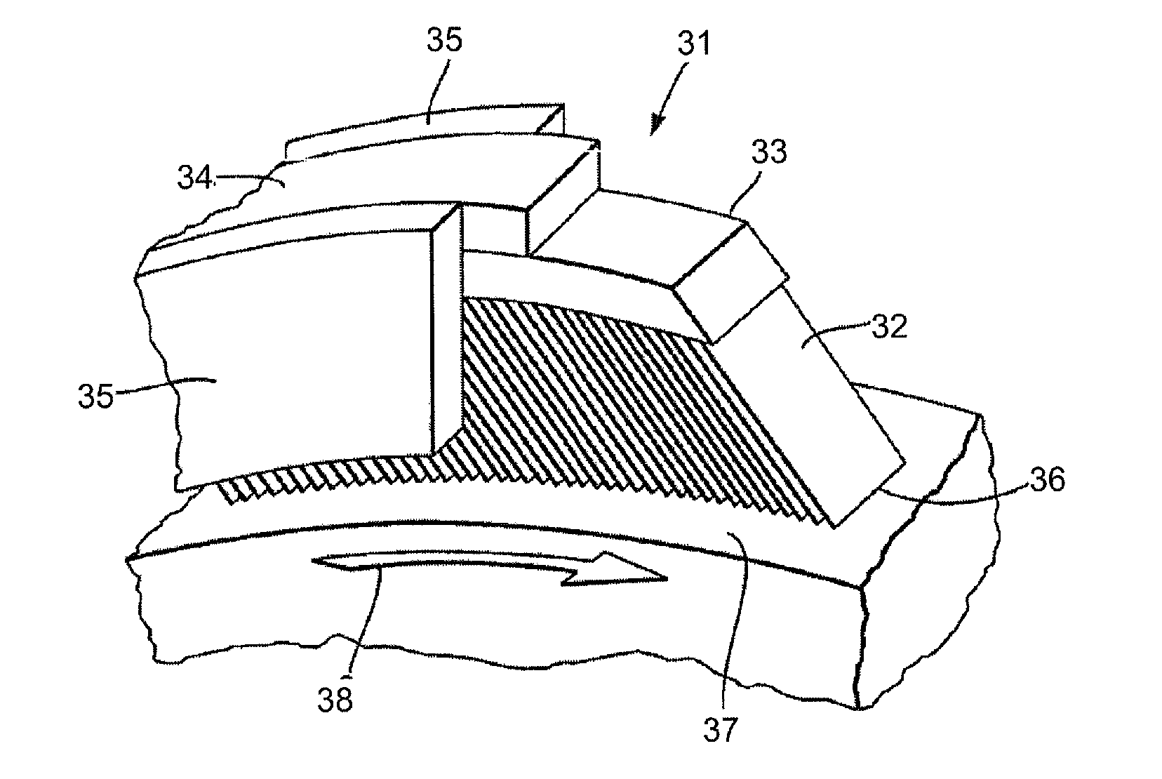
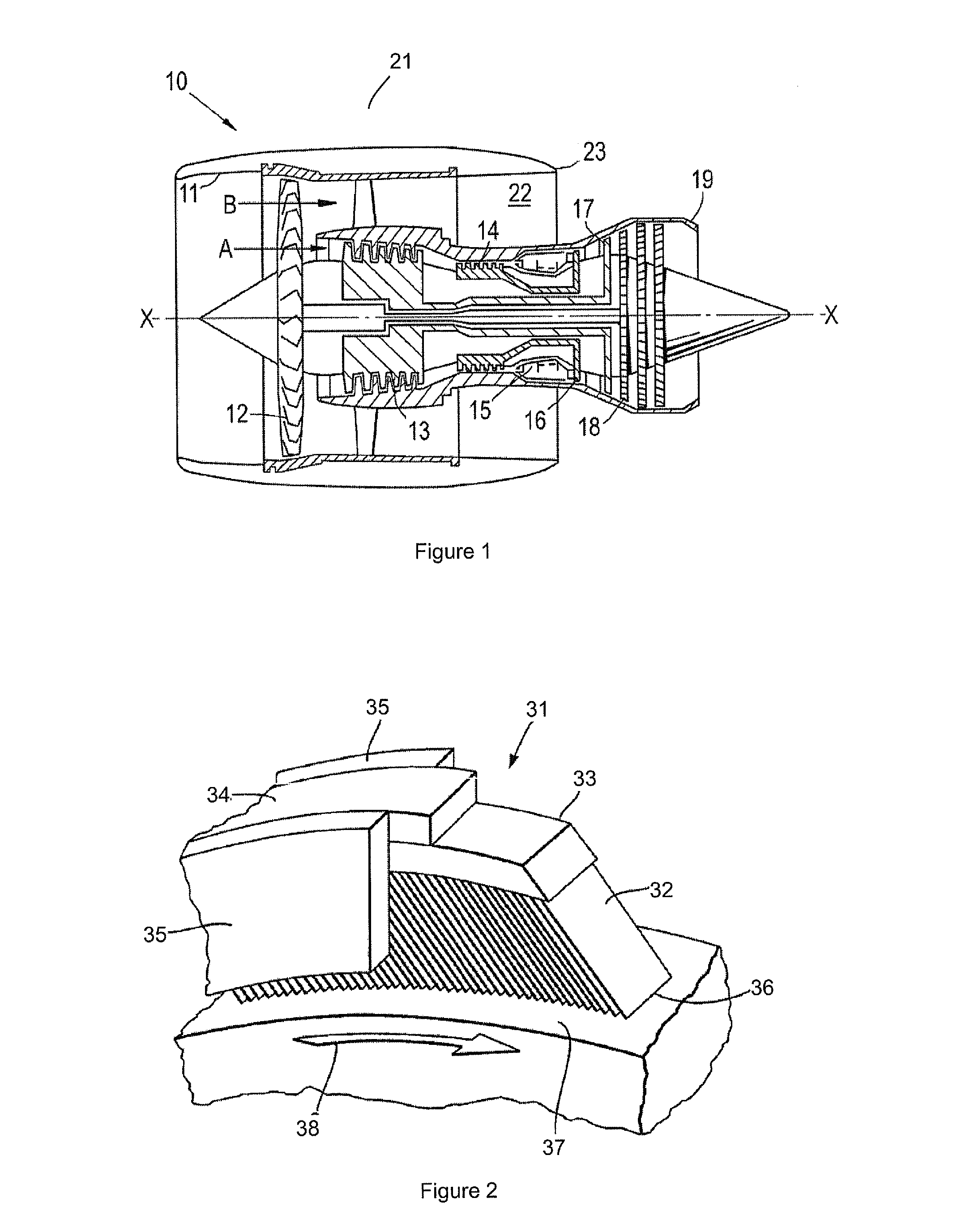
[0039]FIG. 5 shows schematically a view of part of an annular leaf pack for a seal according to the present invention. The leaves 42 of the pack are mounted at respective root portions 49 to a radially outer stationary housing (not shown) and extend towards leaf edges 46 that make wiping contact with the surface 47 of a radially inner rotor.

[0040]Spacers 43 are positioned around the pack after every second root portion. The spacers thus divide the pack into a plurality of leaf blocks, each containing two leaves 42 making face-to-face contact with each other over their entire length from their root portions 49 to their edges 46. The spacers also form interleaf gaps 50 between the end leaves of adjacent blocks, the gaps allowing an axial leakage flow through the pack.

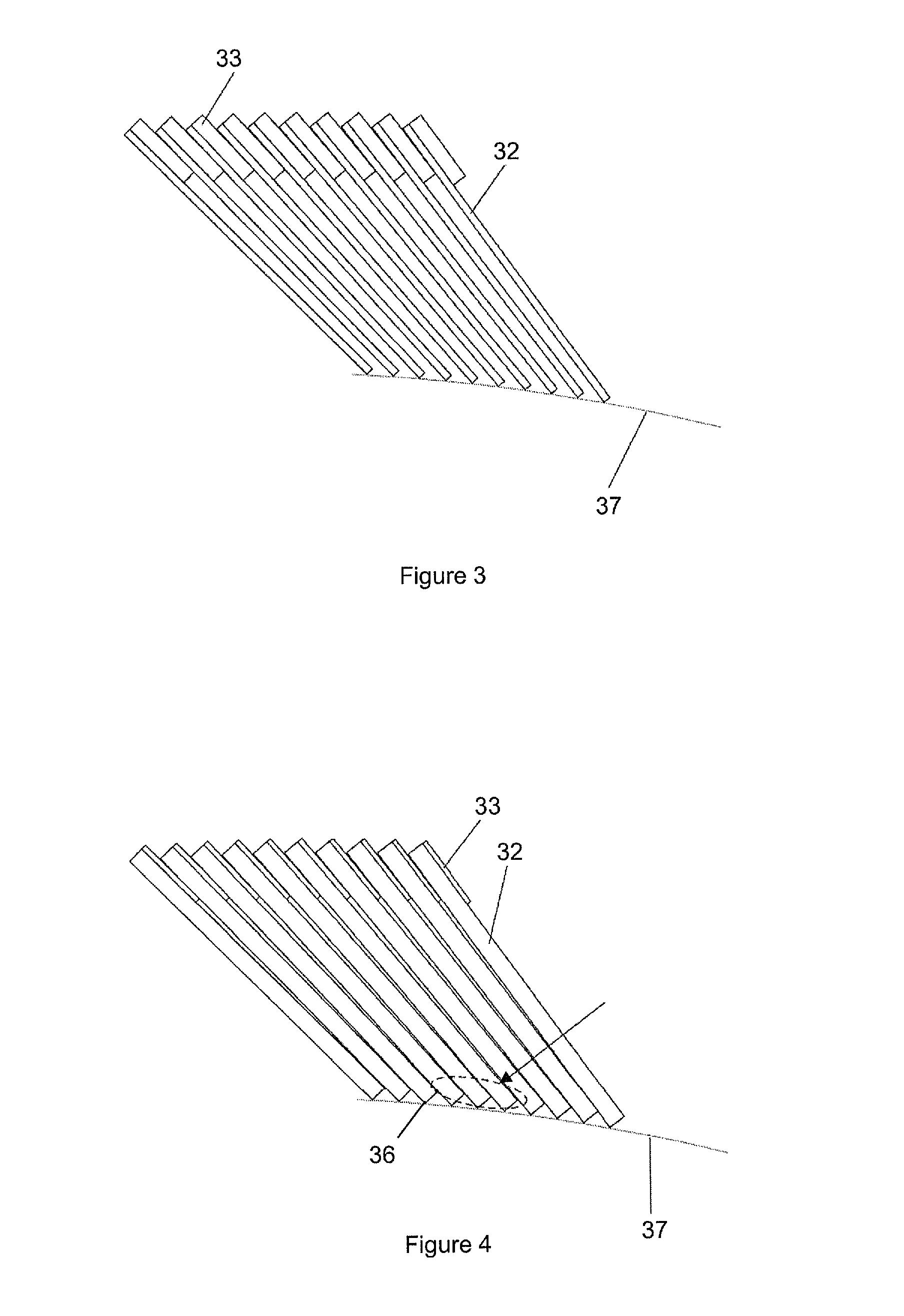
[0041]FIG. 6 shows schematically the leaf pack of FIG. 5 before final assembly into a housing (not shown) comprising typically a backing ring and coverplates. In variants of the leaf pack, the spacers 43 can be positioned...

third embodiment

[0045]The concept of distributing the spacers around a leaf pack so that the leaves are divided into blocks of two or more leaves sandwiched at their root portions between nearest-neighbour spacers can be extended to seals having a plurality of leaf packs. For example, in relation to a seal according to the present invention and having three axially spaced annular packs, FIG. 10 shows schematically (a) a T-shaped lamella and an inverted-U-shaped lamella for forming the leaves of the packs, and (b) the lamellae in readiness for assembly. Each T-shaped lamella provides a leaf 42 and two spacer portions 51 which extending laterally from either side of the root portion of the leaf. Each inverted-U-shaped lamella provides two leaves 42′, 42″ and a spacer portion 51 which bridges the root portions of the leaves. The lamellae are assembled such that the leaves of the T-shaped lamellae form a central leaf pack and the spacer portions of the T-shaped lamellae form spacers between leaves of o...

fourth embodiment

[0047]In a similar fashion, FIG. 14 shows schematically (a) an M-shaped lamella, and (b) inverted-U-shaped, T-shaped and M-shaped lamellae in readiness for assembly according to a variant of FIG. 11. By increasing the number of T-shaped lamellae compared to inverted-U-shaped lamellae, as shown in FIG. 14, improved leakage characteristics and vibration resistance compared to the seal of FIG. 12 may be achieved while still maintaining a stiffer central leaf pack.

[0048]In relation to both the third and fourth embodiments, rather than increasing the number of T-shaped lamellae relative to the number of inverted-U-shaped lamellae, it is possible to increase the number of inverted-U-shaped lamellae relative to the number of T-shaped lamellae in order to stiffen the outer packs relative to the central pack.

[0049]While the invention has been described in conjunction with the exemplary embodiments described above, many equivalent modifications and variations will be apparent to those skilled...


PUM


Abstract

A leaf seal is provided for effecting a seal between two coaxial, relatively rotating components. The leaf seal has an annular pack of leaves which are stacked face-to-face within the pack, and which are mountable to one of the components at respective root portions of the leaves such that the leaves extend towards the other component and respective edges of the leaves are presented for wiping contact with the other component. The pack includes a plurality of spacers, each spacer separating the root portions of neighbouring leaves to form therebetween interleaf gaps which allow an axial leakage flow through the pack. The spacers are distributed around the pack such that the leaves are divided into blocks of two or more leaves sandwiched at their root portions between nearest-neighbour spacers.

Description

FIELD OF THE INVENTION[0001]The present invention relates to a leaf seal for effecting a seal between two coaxial, relatively rotating components.BACKGROUND OF THE INVENTION[0002]With reference to FIG. 1, a ducted fan gas turbine engine generally indicated at 10 has a principal and rotational axis X-X. The engine comprises, in axial flow series, an air intake 11, a propulsive fan 12, an intermediate pressure compressor 13, a high-pressure compressor 14, combustion equipment 15, a high-pressure turbine 16, and intermediate pressure turbine 17, a low-pressure turbine 18 and a core engine exhaust nozzle 19. A nacelle 21 generally surrounds the engine 10 and defines the intake 11, a bypass duct 22 and a bypass exhaust nozzle 23.[0003]The gas turbine engine 10 works in a conventional manner so that air entering the intake 11 is accelerated by the fan 12 to produce two air flows: a first air flow A into the intermediate pressure compressor 13 and a second air flow B which passes through t...

Claims


Application Information

Patent Timeline
IPC IPC(8): F02C7/28
CPCF16J15/3292F02C7/28
Inventor JAHN, INGO HENRY JOHANNES
Owner ROLLS ROYCE PLC
Why Eureka
Try Eureka