Fiber-optic surface plasmon resonance sensor and sensing method using the same

a technology of surface plasmon and sensor, which is applied in the direction of instruments, cladded optical fibres, optical elements, etc., can solve the problems of high cost, inconvenient point-of-care diagnosis or remote sensing, complex system configuration, etc., and achieve excellent tunability of surface plasmon resonance wavelength, improve sensitivity of fiber-optic sensors, and increase the thickness of optical waveguide layers

Active Publication Date: 2013-05-16
KOREA INST OF SCI & TECH
View PDF9 Cites 38 Cited by
  • Summary
  • Abstract
  • Description
  • Claims
  • Application Information

AI Technical Summary

Benefits of technology

[0017]The fiber-optic surface plasmon resonance sensor and the sensing method according to the embodiments of the invention may provide excellent tunability of surface plasmon resonance wavelength through control of the thickness of the optical waveguide layer of the surface plasmon excitation layer. Furthermore, self-calibration is possible using the waveguide mode generated in the optical waveguide layer due to the s-polarized light, and multiple surface plasmon resonance modes may be generated by increasing the thickness of the optical waveguide layer and the modes may be used selectively. In addition, since the surface plasmon resonance condition can be fine-tuned over a broad range, the sensitivity of the fiber-optic sensor can be remarkably improved and a fiber-optic surface plasmon resonance sensor operable in the near infrared to mid-infrared region where the superior sensitivity to the change in external environment, local electric field penetration depth and molecular selectivity can be provided.

Problems solved by technology

On the other hand, since it requires a high-precision two-axis goniometer and a control system therefor, the cost is high and the system configuration is complicated and bulky.
Accordingly, it is not suitable for point-of-care diagnosis or remote sensing.
However, the conventional fiber-optic surface plasmon resonance sensor has several problems.
This suggests that the change in resonance wavelength is quite limited even when the multi-mode optical fiber with relatively large numerical aperture is used.
In this case, it is very difficult to fine-tune the resonance condition to optimize the signal intensity for the conventional fiber-optic surface plasmon resonance sensor.
Such requirements cause a burden in process.

Method used


Image

  • Fiber-optic surface plasmon resonance sensor and sensing method using the same
  • Fiber-optic surface plasmon resonance sensor and sensing method using the same
  • Fiber-optic surface plasmon resonance sensor and sensing method using the same

Examples


Embodiment Construction

[0031]Hereinafter, exemplary embodiments will be described in detail with reference to the accompanying drawings.

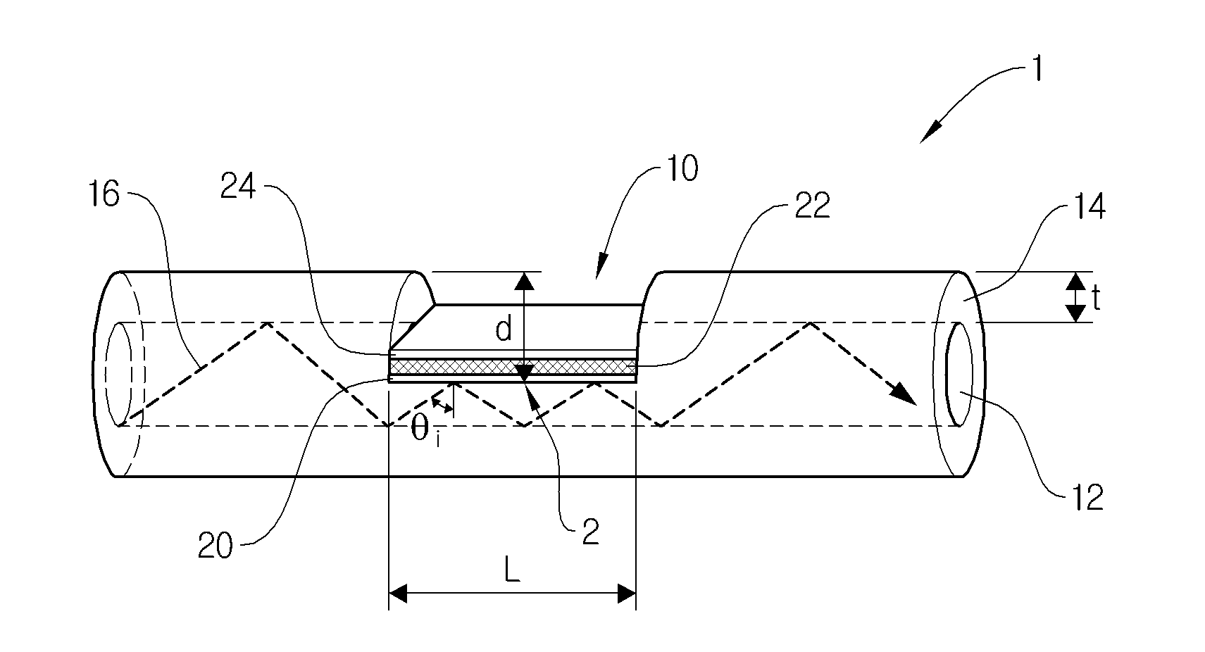
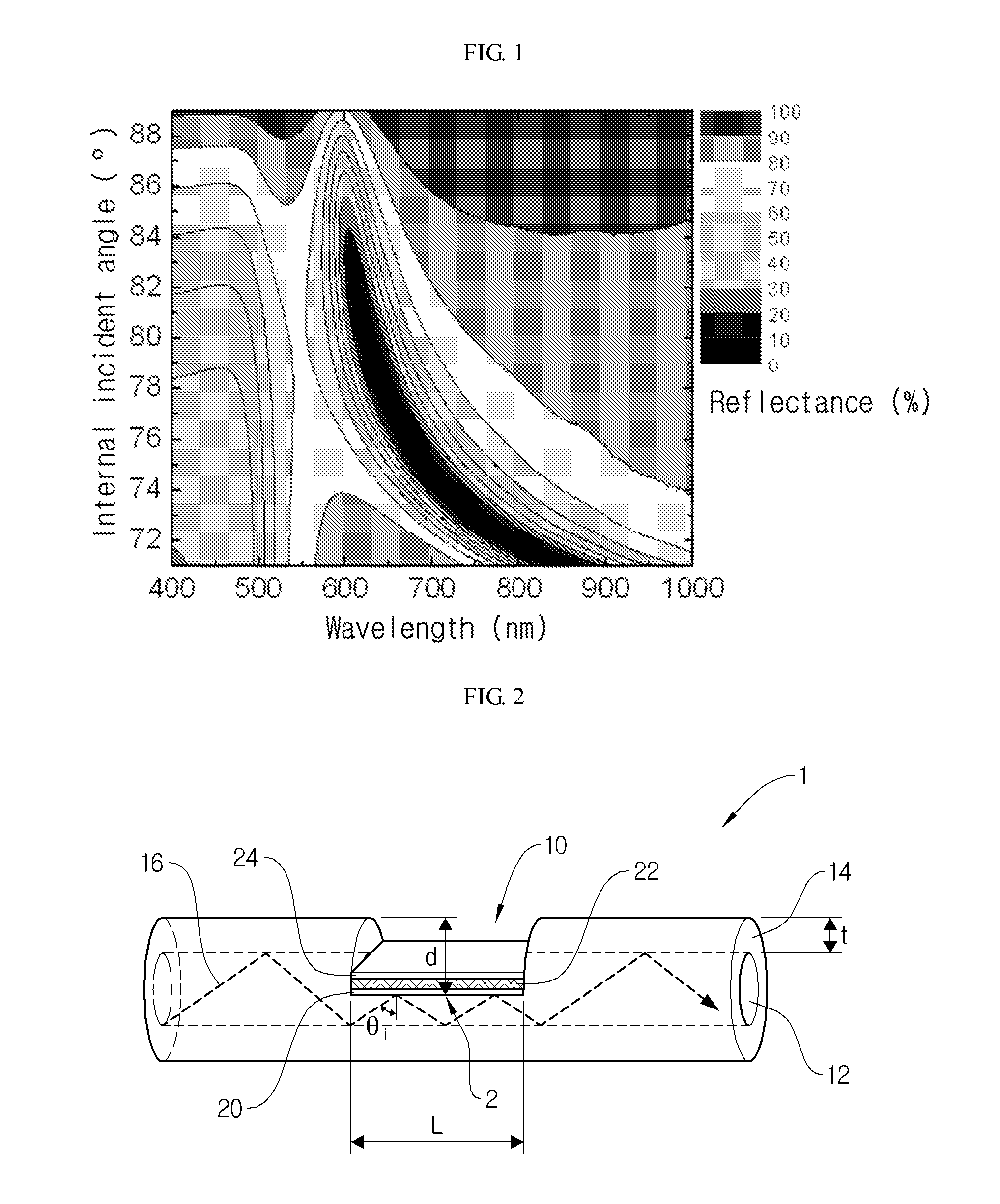
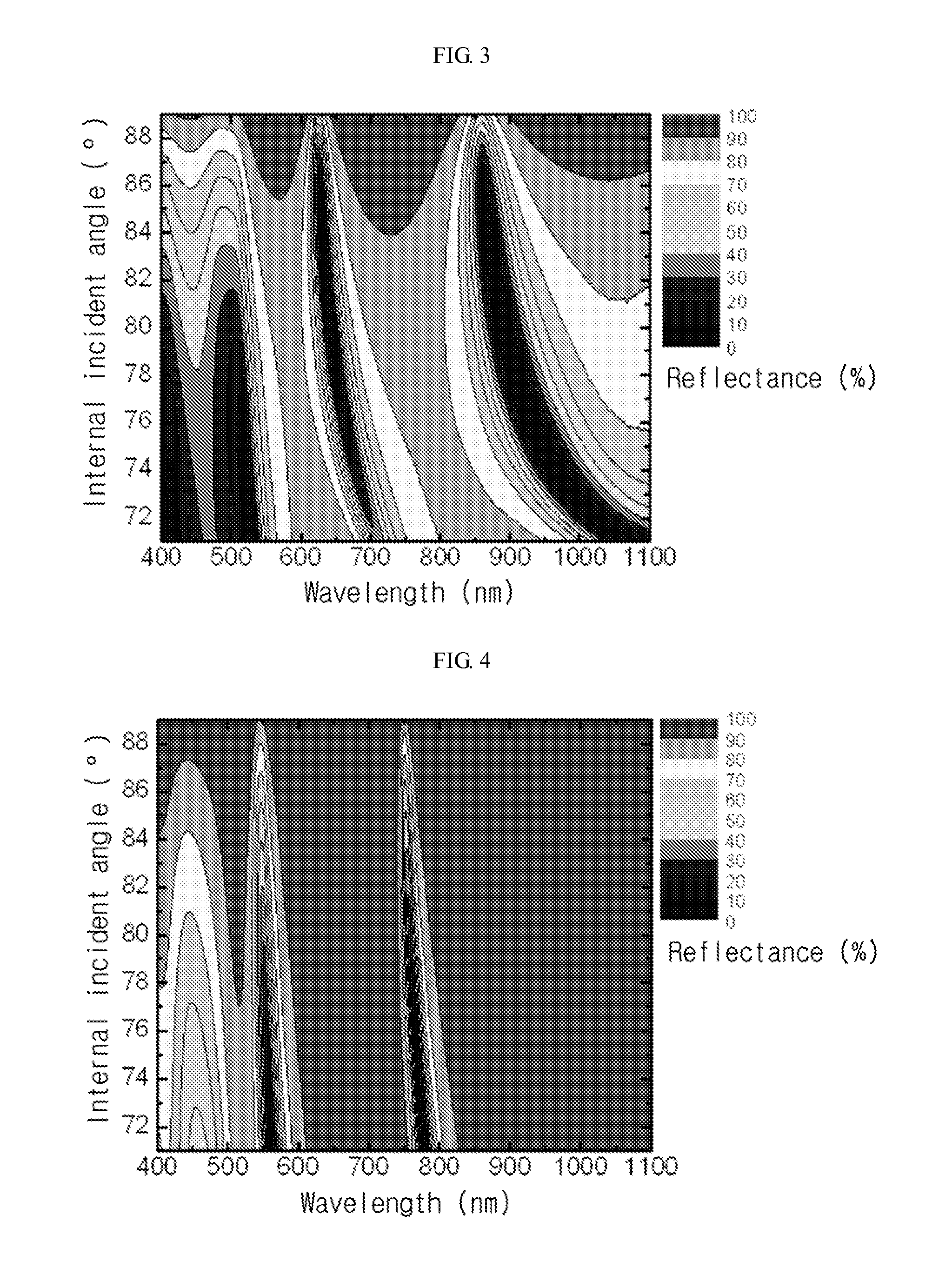
[0032]FIG. 2 schematically shows the configuration of a fiber-optic surface plasmon resonance sensor according to an exemplary embodiment.

[0033]Referring to FIG. 2, a fiber-optic surface plasmon resonance sensor according to an exemplary embodiment may include an optical fiber 1 and a surface plasmon excitation layer 2. The optical fiber 1 may include a core 12, a cladding 14 and a depression 10. The core 12 and the cladding 14 may extend along one direction, and the cladding 14 may be disposed to surround the core 12. The core 12 may include any material which is optically transparent at an operation wavelength. The cladding 14 may include any material whose refractive index is lower than the refractive index of the core 12.

[0034]The depression 10 may be formed on a side surface of the optical fiber 1, i.e. in a direction perpendicular to the length direction of the opti...


PUM

PropertyMeasurementUnit
internal incident angleaaaaaaaaaa
surface plasmon resonance wavelengthaaaaaaaaaa

Abstract

A fiber-optic surface plasmon resonance sensor may include an optical fiber and a surface plasmon excitation layer. The optical fiber may include a core, a cladding surrounding the core, and a depression. The surface plasmon excitation layer may include a first excitation layer, a second excitation layer and an optical waveguide layer between the first excitation layer and the second excitation layer. Incident light incident through the core may be coupled to the surface plasmon excitation layer at a specific angle of incidence and wavelength satisfying the surface plasmon resonance condition. Depending on the polarizing direction of the incident light, an s-polarized component may be coupled to the guided-wave mode in the optical waveguide layer constituting the surface plasmon excitation layer.

Description

CROSS-REFERENCE TO RELATED APPLICATIONS[0001]This application claims priority under 35 U.S.C. §119 to Korean Patent Application No. 10-2011-117414, filed on Nov. 11, 2011, in the Korean Intellectual Property Office, the disclosure of which is incorporated herein by reference in its entirety.BACKGROUND[0002]1. Field[0003]Embodiments relate to a fiber-optic surface plasmon resonance sensor and a sensing method using the same.[0004]2. Description of the Related Art[0005]A surface plasmon resonance sensor is a sensor utilizing the phenomenon that the excitation condition of surface plasmons, which are charge density waves of free electrons generated on the surface of a metal film at a metal-dielectric interface, is very sensitive to the change in surrounding environments. Biosensors and environmental sensors based on surface plasmon resonance are extensively studied.[0006]The conventional surface plasmon resonance sensor has a structure including a prism with a high refractive index and...

Claims


Application Information

Patent Timeline
Patent Type & Authority Applications(United States)
IPC IPC(8): G01N21/55
CPCG02B6/1226G02B6/02G01N21/553G02B5/008
Inventor LEE, KYEONG SEOKKIM, WON MOKLEE, TAEK SUNGKIM, IN HO
Owner KOREA INST OF SCI & TECH
Why Eureka
Try Eureka