Ocean wave power plant

a technology of power plants and ocean waves, applied in the direction of electric generator control, machines/engines, mechanical equipment, etc., can solve the problems of increasing the cost of building the installation, the efficiency of such installations, and the cost of maintaining the installation, so as to reduce the need for maintenance and reduce the loss of produced power , the effect of cost-effectiveness

Active Publication Date: 2013-05-23
DRAGIC MILE
View PDF13 Cites 50 Cited by
  • Summary
  • Abstract
  • Description
  • Claims
  • Application Information

AI Technical Summary

Benefits of technology

[0028]The invention is particularly, but not exclusively, advantageous for obtaining a cost effective ocean power plant with reduced needs for maintenance, which at the same time reduces loss of produced power due to simplifications of respective operative mechanical parts and interconnections of respective mechanical parts.
[0029]According to an example of embodiment of the present invention an ocean wave power plant is provided for by respective interconnected functional units comprising a support structure 1a, 1b terminated in a lower end with a fastening bracket 9c to be anchored in a single point to a mass 9e when deployed in the sea, a submergible uplift floating body 2 providing buoyancy for the ocean wave power plant when deployed in the sea, wherein the uplift floating body 2 is attached to the support structure 1a, 1b, an electric power generating subsystem A supported by a platform 8 terminating the support structure 1a, 1b in an upper end of the support structure, a transmission member 4, 4a, 18 is attached in one end to a floating body 3 and in another end to the power generating subsystem A transferring wave motion from the floating body 3 to the power generating subsystem A, wherein the support structure 1a, 1b, the floating body 3, the uplift floating body 2, the fastening bracket 9c, the power generating subsystem A, the mass 9e, at least a part of the transmission member 4, 4a, 18 is arranged functionally interconnected along a common axis, wherein each respective functional unit is arranged as weight symmetrically as possible around the common axis, wherein the support structure 1a, 1b is guided through a through hole in the floating body 3 and is fastened to the uplift floating body 2, wherein a motion constraining device 100 is arranged in the centre of the through hole, wherein the part of the transmission member 4, 4a, 18 that is arranged along the common axis in one end is connected to a centre point on a top side of the motion constraining device 100, and correspondingly further is continued to be arranged along the common axis from a connection to an opposite located centre position on a bottom side of the motion constraining device 100. The term “motion constraining device” referenced with the numeral 100 is to be understood to comprise all necessary arrangements and variations of arrangements for connecting the floating body to a transmission member in such a way that the motion up and down of the floating body provides optimized transfer of energy from the ocean waves. It is to be understood that the word “constraining” defines allowed movements in all directions of the floating body but with the “constraint” to optimize the transfer of energy. For example, an elongated shaped floating body will turn its longer side towards an incoming wave front. This is actually an optimized positioning of such a floating body to be able to optimize transfer of energy. Therefore it is important to “constrain” the motion in the horizontal plane to be free rotating such that an optimized positioning may be achieved. However, there will be a simultaneous tilting of the elongated shaped floating body in a vertical plane due to wave motions. Therefore, the tilting must be constrained not to harm the installation it is connected to. It is also important that this vertical constrainment do not have an impact on the horizontal motion. Even though it is possible to use a round shaped floating body the same arguments may be used for the same type of constrainment of the motion in the respective horizontal and vertical plane. However, free rotation in the horizontal plane should be allowed to mitigate abrupt changes of wave patterns which otherwise could be transferred to the installation if the horizontal motion was not free. In this context the term “motion constraining device” or “motion constraining arrangement” is meant to comprise any physical effect that is utilized to “constrain” the movement of the floating body in all directions, first of all to optimize transfer of energy but also to take into account possible safety issues.

Problems solved by technology

However, there are very few commercial successfully installations of ocean power plants.
This implies that an ocean wave power plant needs to be a durable and strong construction which increases the cost of building the installation and also often the cost of maintaining the installation.
Even though the functioning of a wave power plant is simple to understand for a person skilled in the art it has proved to be a challenge to improve the efficiency of such installations.
The fixed position of the pylon by the anchoring makes the design vulnerable to harsh weather conditions and the pylon must be able to resist strong forces due to possible huge waves.
However, the design is intended only for shallow water close to beaches and the design with a defined length of the arm with two opposite located floats makes it only operate properly at certain ocean wave frequencies.
However, the connection point of the shaft to the top surface of the float is subject to strong forces from wave motions and lateral force components from the wave motions may tend to provide ware and tear of the shaft connection of the rack and pinion gear.
However, the installation tends to be very large covering a substantial part of the ocean surface.
Therefore, the cost is high and maintenance is a problem in an interconnected system when a module that is surrounded by other modules need service.
This may imply a costly design of for example the top beam to provide a stable design that can withstand the size and weight of the floating body, different weather conditions, and at the same time deliver on target for the power production.
However, these prior art engine solutions requires for example that a rod connected to a piston in the engine can move back and forth in a direction perpendicular to the direction of the movements back and forth of the piston to be able to turn a cam shaft in the engine into a unidirectional rotation.
If this additional freedom of motion is constrained, this solution of transforming the piston movement into a unidirectional rotational motion of a shaft is difficult to achieve.
However, it is well known by a person skilled in the art that any gear and shaft connection provides a sort of friction in a mechanical system, which in this case provides a loss or decrease of possible power output from an ocean wave power plant.
Further, it is obvious that any design that reduces the number of gears that are necessary to use in an ocean wave power plant actually increases the efficiency of the power production itself.
Further, in wave power plants shafts etc. are subject to variable speeds due to variable wave conditions.
These variations can be abrupt and therefore damage on different parts of a wave power plant may appear as known in prior art, for example.
Therefore, the use of a cam shaft as known from motor engines is for example difficult to use as readily understood by a person skilled in the art.
However, the possible large amplitudes of the waves and the corresponding strong forces make these designs very complicated.
The consequence is not that such designs will not function, but that there might be a significant loss of power in the conversion chain due to the number of parts, size of parts etc.
It is also a design challenge that the amplitude of the ocean waves might be small.
However, it is a challenge to meet the requirement of providing both buoyancy and weight.
However, the increased weight of the floating body may make the floating body subject to damages when experiencing slamming.
Slamming is a well known problem in ship design and off shore design.
This impact can provide damages to the installation and the floating body itself.
Therefore, safety issues provides that if a floating body leaps out of water the water inside the floating body should be emptied to mitigate the effect of possible slamming.
However, there is no indication how to provide a technical solution providing this kind of optimization of energy extraction.

Method used


Image

  • Ocean wave power plant
  • Ocean wave power plant
  • Ocean wave power plant

Examples


Embodiment Construction

[0066]Although the present invention has been described in connection with specified embodiments, examples of embodiments should not be construed as being in any way limited to the presented examples. The scope of the present invention is set out by the accompanying claim set. In the context of the claims, the terms “comprising” or “comprises” do not exclude other possible elements or steps. Also, the mentioning of references such as “a” or “an” etc. should not be construed as excluding a plurality. The use of reference signs in the claims with respect to elements indicated in the figures shall also not be construed as limiting the scope of the invention. Furthermore, individual features mentioned in different claims, may possibly be advantageously combined, and the mentioning of these features in different claims does not exclude that a combination of features is not possible and / or advantageous.

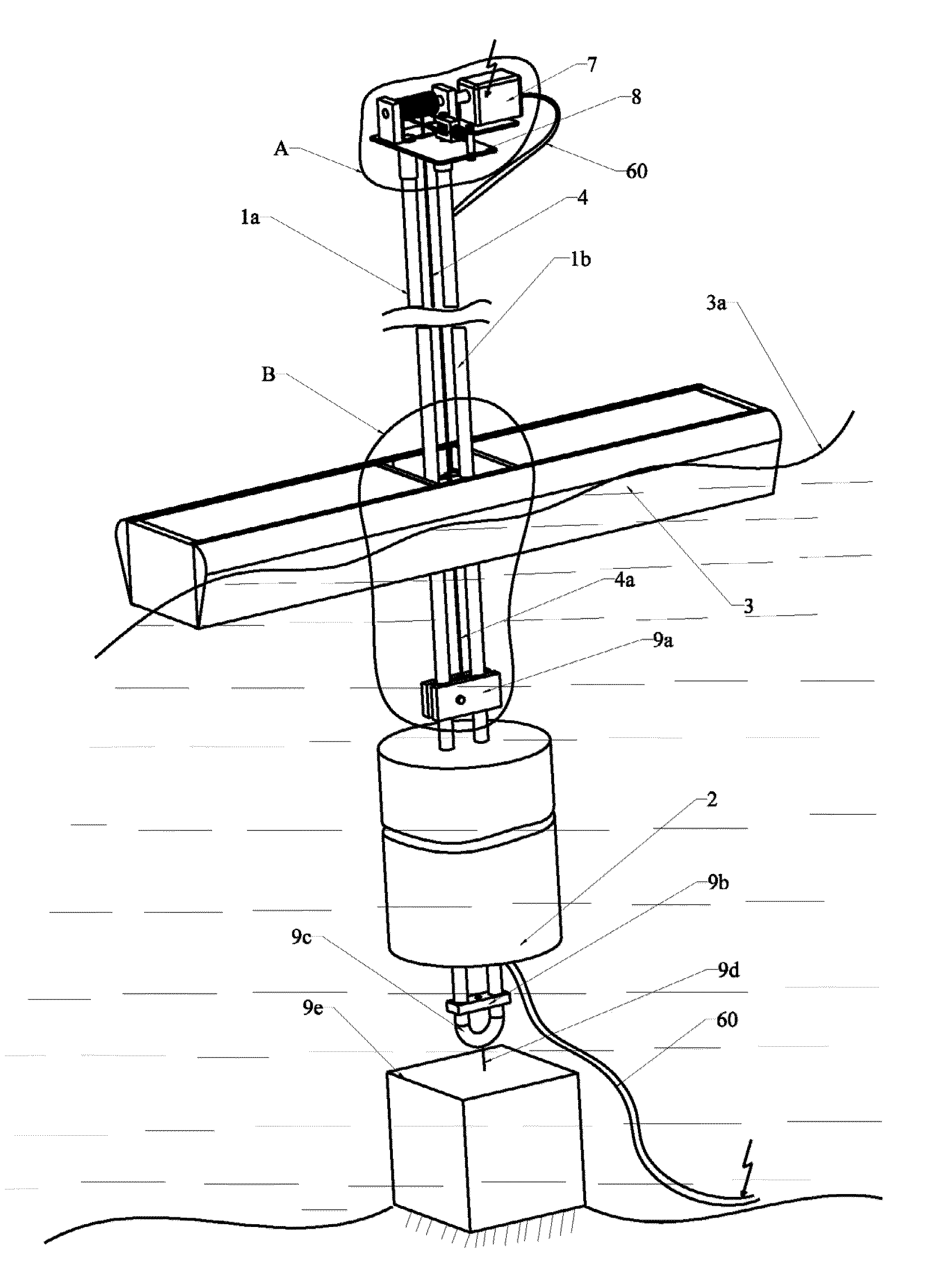
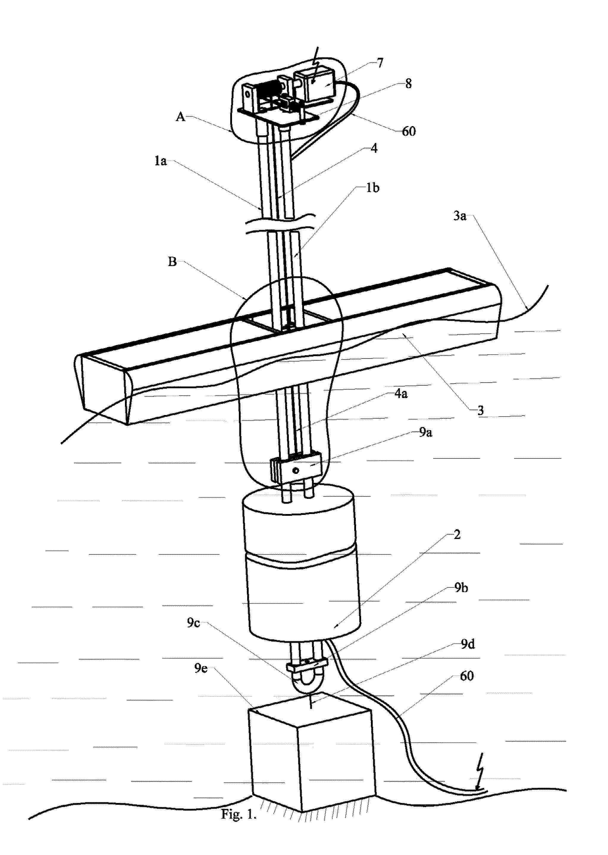
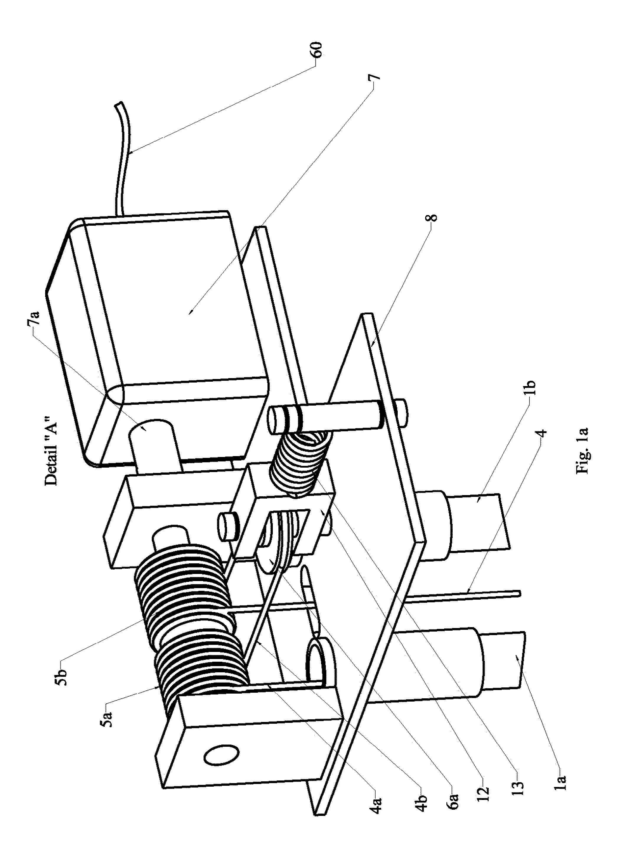
[0067]FIG. 1 illustrates an example of embodiment of the present invention. The design ...


PUM


Abstract

An ocean wave power plant provided for by respective interconnected functional units comprising a support structure (1a, 1b) is disclosed. The support structure (1a, 1b) is terminated in a lower end with a fastening bracket (9c) which can be anchored in a single point to a mass (9e) when deployed in the sea. A submergible uplift floating body (2) is providing buoyancy for the ocean wave power plant when deployed in the sea. The a uplift floating body (2) is attached to the support structure (1a, 1b), an electric power generating subsystem (A) supported by a platform (8) is terminating the support structure (1a, 1b) in an upper end of the support structure. A transmission member (4, 4a, 18) is attached in one end to a floating body (3) and in another end to the power generating subsystem (A) transferring wave motion from the floating body (3) to the power generating subsystem (A).

Description

FIELD OF THE INVENTION[0001]The present invention relates to an ocean wave power plant and a method for deployment thereof, wherein the ocean power plant comprises a floating body collecting wave energy from ocean waves, and especially to an ocean wave power plant comprising at least one support member for the wave power plant, wherein the at least one support member is arranged and located through a centrally located hole in the floating body, wherein the hole in the floating body provides a passage from a top side of the floating body to the bottom side of the floating body, wherein the method comprises steps for attaching a self lifting anchor to the ocean wave power plant, and steps for positioning the ocean power plant on the ocean sea bed using the self lifting anchor.BACKGROUND OF THE INVENTION[0002]Ocean wave power plants of different designs are well known examples of alternative power sources compared to the more traditional power sources in prior art. However, there are v...

Claims


Application Information

Patent Timeline
Patent Type & Authority Applications(United States)
IPC IPC(8): F03B13/18
CPCF03B13/1855F03B13/186Y02E10/38F05B2220/706F05B2260/02F03B13/1885F05B2260/4031Y02E10/30
Inventor DRAGIC, MILE
Owner DRAGIC MILE
Why Eureka
Try Eureka