Position sensor, actuator-sensor device and method for the inductive detection of a position

a position sensor and actuator technology, applied in the direction of electrical/magnetically converting sensor output, electric/magnetic position measurement, instruments, etc., can solve the problems of merely being integrated with a high mounting effort, comparatively high cost, and insufficient size, so as to reduce the voltage of the coil. , the effect of effective solution

Active Publication Date: 2013-05-23
TRW AUTOMOTIVE ELECTRONICS & COMPONENTS GMBH & CO KG
View PDF12 Cites 22 Cited by
  • Summary
  • Abstract
  • Description
  • Claims
  • Application Information

AI Technical Summary

Benefits of technology

[0006]The position sensor according to the aforementioned aspects of the invention is based on the physical effect that in the preferably metallically conductive reference body, which is permeated by the magnetic field of the reference coil, eddy losses are induced and the same lead to an energy loss of the magnetic field. Due to the occurring energy loss the coil voltage is reduced, which can be detected as an input signal indicating the position of the reference body with respect to the reference coil.
[0007]In accordance with aspects of the invention a current impulse is generated in the reference coil, and the occurring energy loss of the magnetic field is detected with reference to the resulting oscillation. It has been recognized that due to parasitic capacitances of the outer wiring and the reference coil a damped oscillation occurs in the same, and this effect can be utilized for the inductive position detection. As compared to solutions known from the prior art, the position sensor according to aspects of the invention has the advantage that the reference coil can be dimensioned smaller. In addition, a smaller coil excitation current and a smaller excitation frequency can be used. This is advantageous in particular with regard to the electromagnetic compatibility (EMC) of the position sensor.
[0008]The control and processing unit also can be designed to evaluate an amplitude of the oscillation generated by the current impulse in the reference coil. The height of this amplitude can be regarded as a measure for the energy loss caused by the reference body. An evaluation of the amplitude as an input signal indicating the position of the reference body therefore represents a particularly effective solution.

Problems solved by technology

However, the sensors mentioned above merely can be realized with comparatively high costs, in addition have a too large size and can merely be integrated with a high mounting effort.
Sensors operating in a capacitive manner also are sensitive to moisture.

Method used


Image

  • Position sensor, actuator-sensor device and method for the inductive detection of a position
  • Position sensor, actuator-sensor device and method for the inductive detection of a position
  • Position sensor, actuator-sensor device and method for the inductive detection of a position

Examples


Embodiment Construction

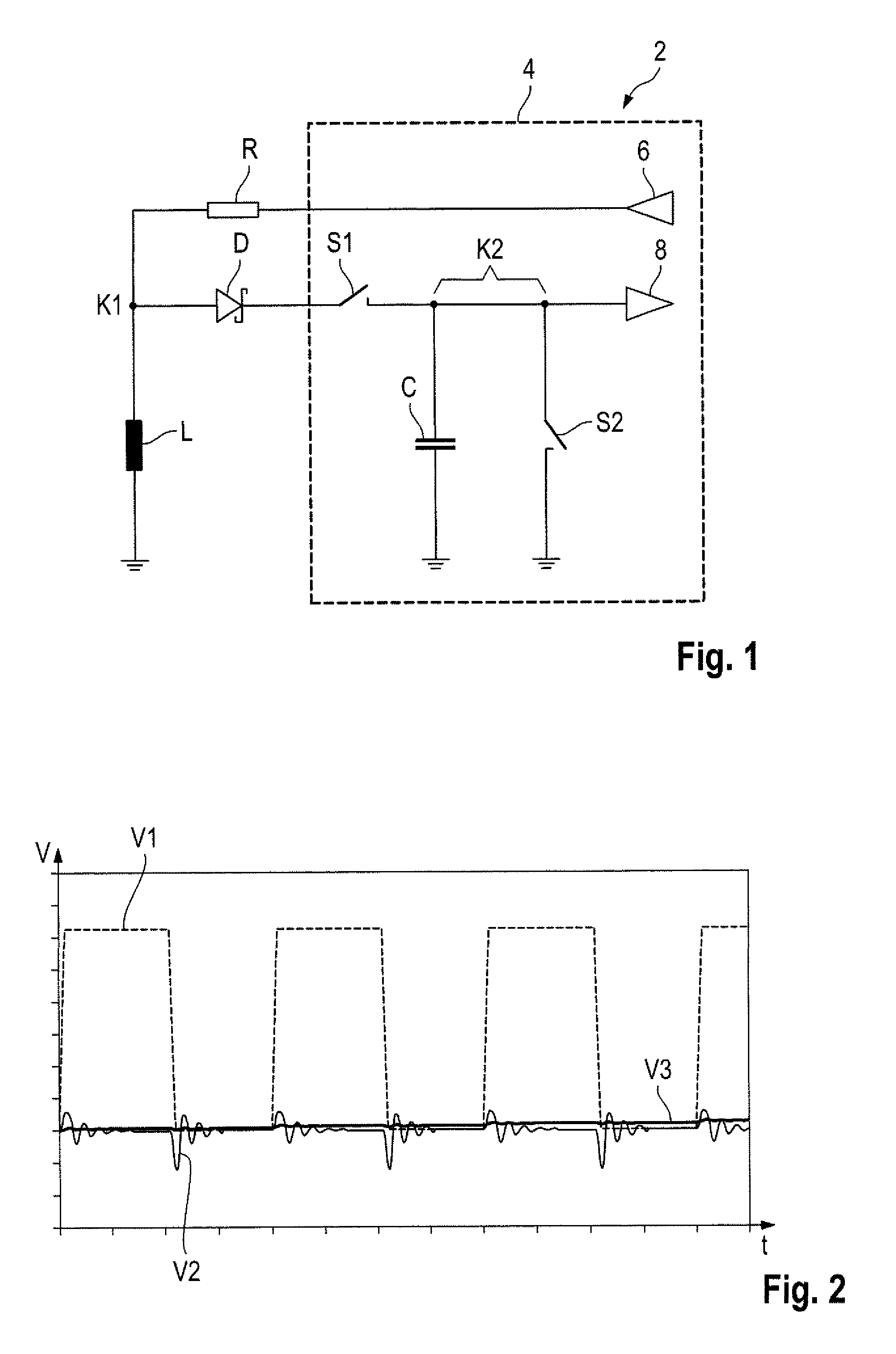
[0034]FIG. 1 shows a simplified circuit diagram of a position sensor 2, which includes a control and processing unit 4, with an output 6, preferably a digital output, and with an input 8 which for example is coupled to an AID converter. In the following, it is assumed by way of example that the control and processing unit 4 is a microcontroller 4. Via a resistor R, its output 6 is coupled with a first node K1 with which in addition a first side of a reference coil L is coupled, whose other side is connected to a fixed reference potential, in this case to ground. With the first node K1 a diode D in addition is connected, which acts as rectifier diode and which preferably is a Schottky diode. The diode D is connected in forward direction between the first node K1 and a second node K2. Into this connection a first switch S1 is integrated. With the second node K2 a capacitor C with a capacitance between 10 and 20 pF and a second switch S2 are coupled in addition. As switches S1, S2, MOS...


PUM


Abstract

A position sensor for the inductive detection of a position of a first component comprising a reference coil with respect to a second component comprising a reference body. A control and processing unit of the position sensor is coupled to the reference coil and is designed for issuing an output signal generating a current impulse in the reference coil. In addition, the control and processing unit is designed for evaluation of an oscillation generated by the current impulse in the reference coil as an input signal indicating the position of the reference body.

Description

BACKGROUND OF THE INVENTION[0001]This invention relates to a position sensor for the inductive detection of a position of a first component comprising a reference coil with respect to a second component comprising a reference body. The invention also relates to an actuator-sensor device and to a method for the inductive detection of a position of a reference body with respect to a reference coil.[0002]Position sensors operating in a contactless manner are employed in many fields of technology. In automotive engineering, contactless position sensors are employed for example as rotary switches or push buttons free from contact wear, in particular for rotary light switches. Such position sensors operate by using various physical measurement principles. Examples include an optical, capacitive or potentiometric measurement. However, the sensors mentioned above merely can be realized with comparatively high costs, in addition have a too large size and can merely be integrated with a high ...

Claims


Application Information

Patent Timeline
Patent Type & Authority Applications(United States)
IPC IPC(8): G01D5/22
CPCG01D5/2291G01B7/30G01B7/023G01B7/003G01D5/2006
Inventor BACKES, ULRICH
Owner TRW AUTOMOTIVE ELECTRONICS & COMPONENTS GMBH & CO KG
Why Eureka
Try Eureka