Wavelength selective optical switching devices

a selective optical and switch device technology, applied in the field of wavelength selective optical switch devices, can solve the problems of insertion loss, difference in the loss of s polarized beam and p polarized beam, and the complexity of the optical network, so as to reduce the loss and polarization dependent loss

Active Publication Date: 2013-05-23
SANTEC
View PDF6 Cites 23 Cited by
  • Summary
  • Abstract
  • Description
  • Claims
  • Application Information

AI Technical Summary

Benefits of technology

[0016]According to one or more embodiments of the present invention having these types of characteristics, light in which incident light has been wavelength dispersed can be made to accommodate a plurality of pixels arrayed in the dispersion direction, and each wavelength component of the incident light can be reflected in different directions by changing the refractive index of the pixels. Further, as this is configured so as to correct optical image height of s polarized light and p polarized light, loss and polarization dependent loss can be reduced. Accordingly, the present invention is effective in a wavelength selective optical switch, and particularly in a wavelength selective switch having many ports.

Problems solved by technology

Meanwhile, in the field of optical communications, optical networks have become more complicated with advancements in research and development in accelerating transmission rates and new modulation formats in response to demand for transmission capacity in recent years.
If there is a difference in the optical path length of the s polarized light and the p polarized light at this time, the optical image height of the s polarized beam and the p polarized beam will not align when the exiting light is taken into the optical fiber causing a problem of insertion loss.
Furthermore, because the optical image height of the s polarized beam and the p polarized beam does not align, a problem occurs in that a difference in the loss of the s polarized beam and the p polarized beam occurs, which is to say that polarization dependent loss (PDL) occurs.

Method used


Image

  • Wavelength selective optical switching devices
  • Wavelength selective optical switching devices
  • Wavelength selective optical switching devices

Examples


first embodiment

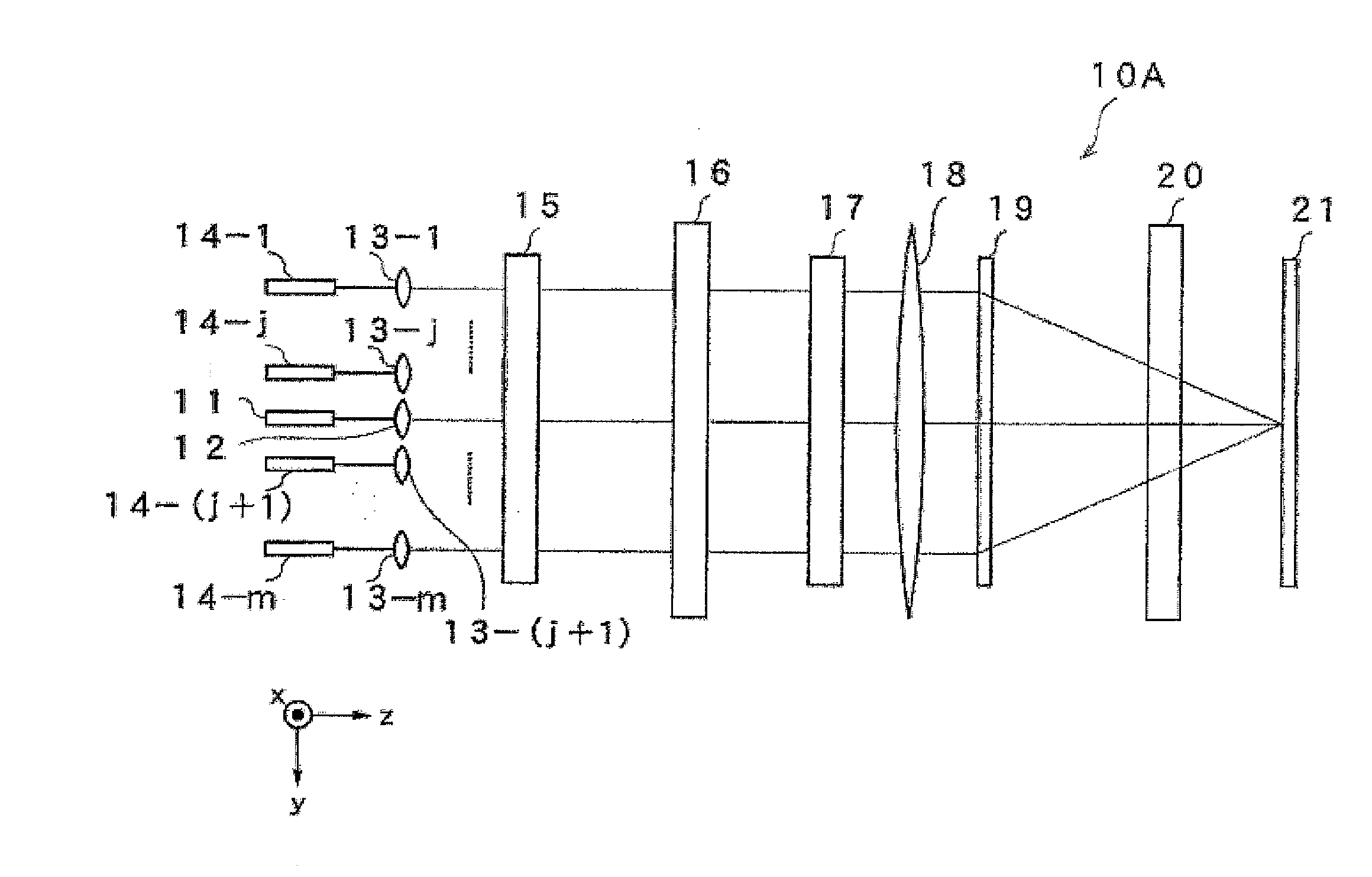
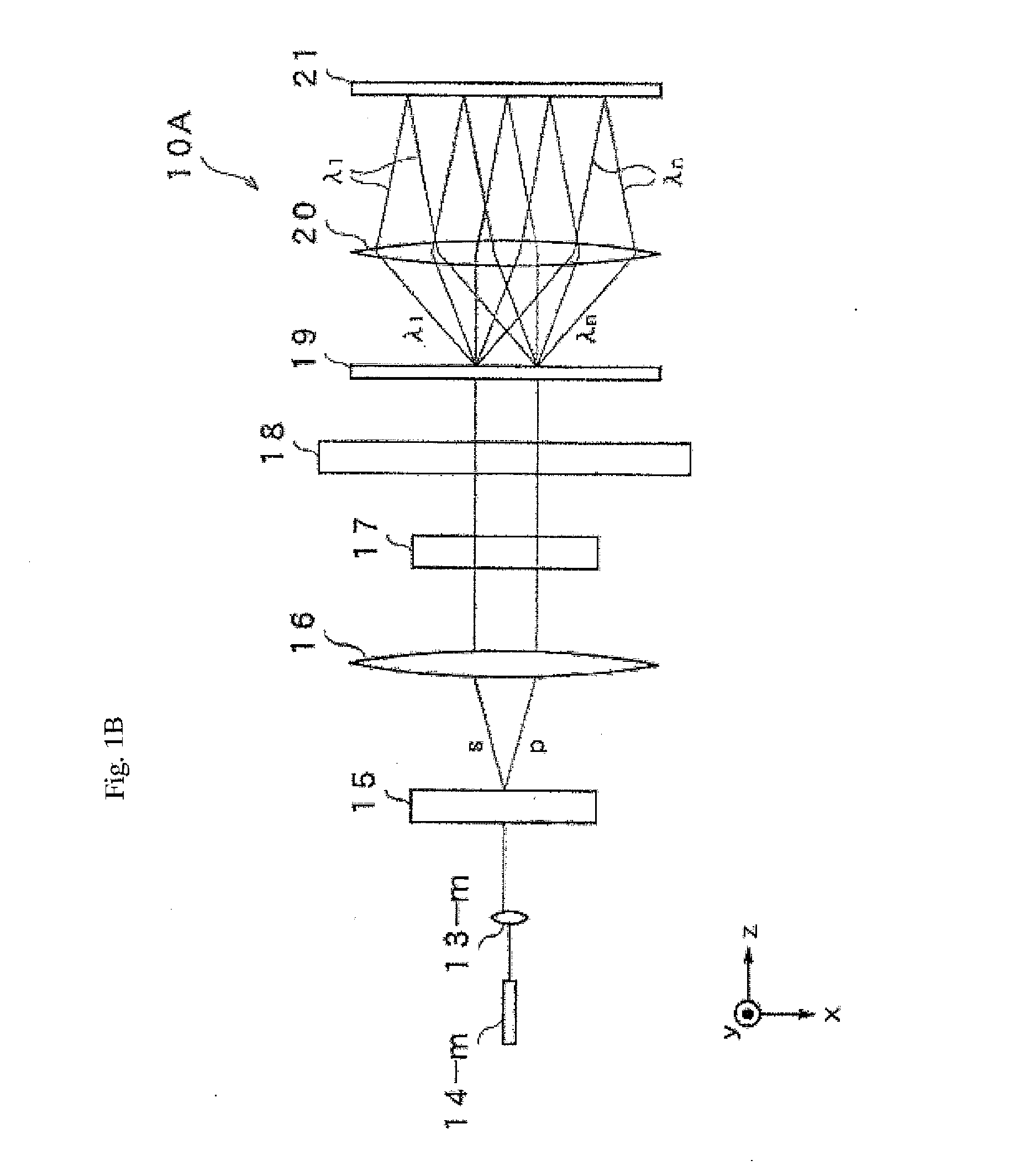
[0028]FIG. 1A is a side view as viewed from the x axis direction illustrating a configuration of an optical element of a reflective type wavelength selective optical switch device 10A according to the first embodiment of the present invention, and FIG. 1B is a side view has viewed from the y axis thereof. The incident light is a multiplexed optical signal of wavelengths λ1 to λn as a WDM signal. The WDM light exits to a collimate lens 12 via optical fiber 11. Further, light that has entered into collimate lenses 13-1 to 13-m adjacent to the collimate lens 12 exits from optical fiber 14-1 to 14-m arranged in parallel to optical fiber 11 respectively. Here, j and m are natural numbers, and J>M. The WDM light that exits into space from the collimate lens 12 is parallel to the z axis, and the WDM light enters into a polarization diversity part 15. The polarization diversity part 15 separates the incident light into an s polarization component and a p polarization component that are the ...

second embodiment

[0030]Next, the description will be given of a wavelength selective optical switch device 10B according to a specific second embodiment of the present invention. FIG. 2 is a side view as viewed from the y axis direction illustrating a configuration of an optical element of a reflective type wavelength selective optical switch device according to the second embodiment of the present invention, and FIG. 3 is a perspective view of an outline thereof. The incident light in FIG. 2 is also a WDM signal as described in the first embodiment, and it enters the collimate lens array 32 from the optical fiber array 31. The optical fiber array 31 has a multiplicity of exiting optical fiber 31-1 to 31-m arranged in parallel to one strand of incoming optical fiber 31a. Furthermore, the collimate lens array 32 has an incoming collimate lens 32a and a number of outgoing collimate lenses 32-1 to 32-m arrayed in parallel, and it corresponds to the collimate lenses 12 and 13-1 to 13-m of the first embo...


PUM

PropertyMeasurementUnit
wavelengthaaaaaaaaaa
wavelengthsaaaaaaaaaa
wavelength dispersionaaaaaaaaaa

Abstract

A wavelength selective switch device includes an incidence part where wavelength multiplexed light made of light of a plurality of wavelengths enters, an exit part that includes a plurality of fiber that outputs light of a wavelength selected from a signal in which wavelength multiplexed light that entered from the incidence part enters, a polarization diversity part that separates incidence light that entered the incidence part according to polarization components of the incidence light to make first and second optical beams, a wavelength dispersion and synthesis element that spatially disperses incidence light according to a wavelength of the incidence light and multiplexes the spatially dispersed reflected light according to the wavelength, and a wavelength dispersion and synthesis element that spatially disperses incidence light according to a wavelength of the incidence light and multiplexes the spatially dispersed reflected light according to the wavelength.

Description

TECHNICAL FIELD[0001]The present invention relates to a wavelength selective optical switch device that uses a liquid crystal element such as liquid crystal on silicon (LCOS) used in the field of optical communications.BACKGROUND TECHNOLOGY[0002]In high speed large capacity optical networks that support today's advanced information and communication companies, wavelength multiplexing optical communication technology is used. Reconfigurable optical add drop multiplexers (ROADM) that provide reconfigurable add drop functionality are being introduced into optical nodes that correspond to branching points of an optical network. Wavelength selective switches (also referred to as WSS) that switch any wavelength in any direction are garnering attention in the implementation of ROADM devices. Optical beam deflection elements that select a wavelength and deflect an optical beam to a desired output port are used in wavelength selective optical switches, and that which uses a diffraction pheno...

Claims


Application Information

Patent Timeline
Patent Type & Authority Applications(United States)
IPC IPC(8): G02F1/1335
CPCG02B6/35G02F1/136277
Inventor SAKURAI, YASUKI
Owner SANTEC
Why Eureka
Try Eureka