Compact, energy-efficient ultrasound imaging probes using cmut arrays with integrated electronics

a technology of ultrasound imaging and integrated electronics, which is applied in the field of ultrasound imaging probes, can solve the problems of limiting the maneuverability of the catheter, only offering side-looking capabilities, and unable to generate images of the volume in front of the catheter, so as to improve the imaging effect, and reduce the sample time

Active Publication Date: 2013-05-23
GEORGIA TECH RES CORP
View PDF3 Cites 25 Cited by
  • Summary
  • Abstract
  • Description
  • Claims
  • Application Information

AI Technical Summary

Benefits of technology

[0011]Embodiments of the present invention relate to ultrasound imaging probes and particularly to forward-looking, energy-efficient ultrasound imaging probes with onboard electronics.

Problems solved by technology

Unfortunately, current commercial IVUS imaging systems offer only side-looking capabilities and cannot generate images of, for example, the volume in front of the catheter.
Current ultrasound array probes used for these purposes are rigid over several millimeters, limiting their maneuverability.
Similarly, for improved flexibility, among other things, the number of electrical connections connecting the probe to the b

Method used


Image

  • Compact, energy-efficient ultrasound imaging probes using cmut arrays with integrated electronics
  • Compact, energy-efficient ultrasound imaging probes using cmut arrays with integrated electronics
  • Compact, energy-efficient ultrasound imaging probes using cmut arrays with integrated electronics

Examples


example 1

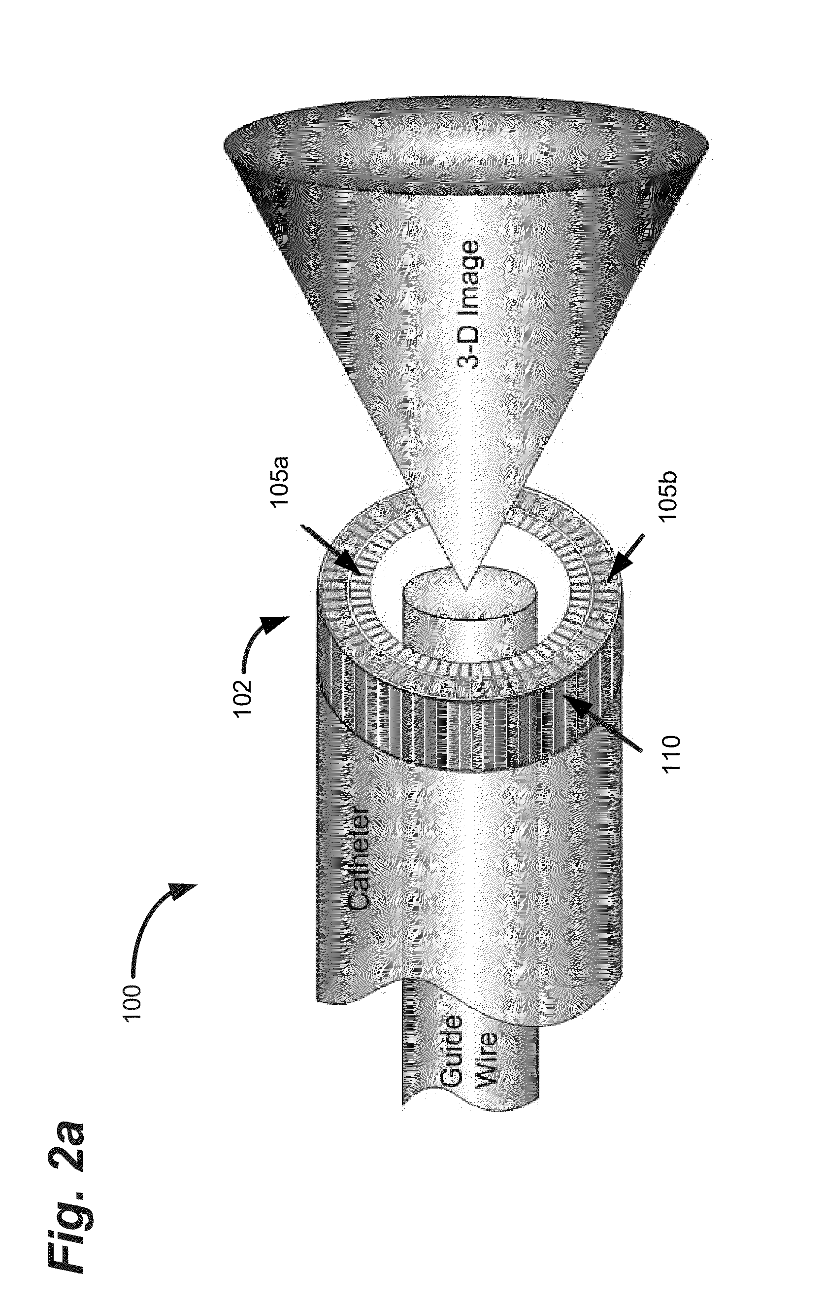
[0064]An example of the type of arrays that can be built using the CMUT technology is schematically shown in FIG. 12a. As shown, five annular rings 1205 can be formed with regular periodicity on a donut shaped silicon region 1200. This configuration is practical for an IVUS probe with a center opening 1210 for a guide wire or intervention tools, for example. Since it would be difficult, if not impossible, to both implement the front end electronics required for a phased array on this silicon chip 1200 and to provide the number of required external electrical connections to take full advantage of all the Tx and Rx elements 1215, in a preferred embodiment, synthetic array processing can be used.

[0065]Numerical modeling tools based on diffraction calculations or available software programs like FIELD-H can be used to evaluate the beam pattern quality and the PSF for a given firing set. In addition, co-array concepts such as those described in Hoctor can be used to obtain non-redundant ...

example 2

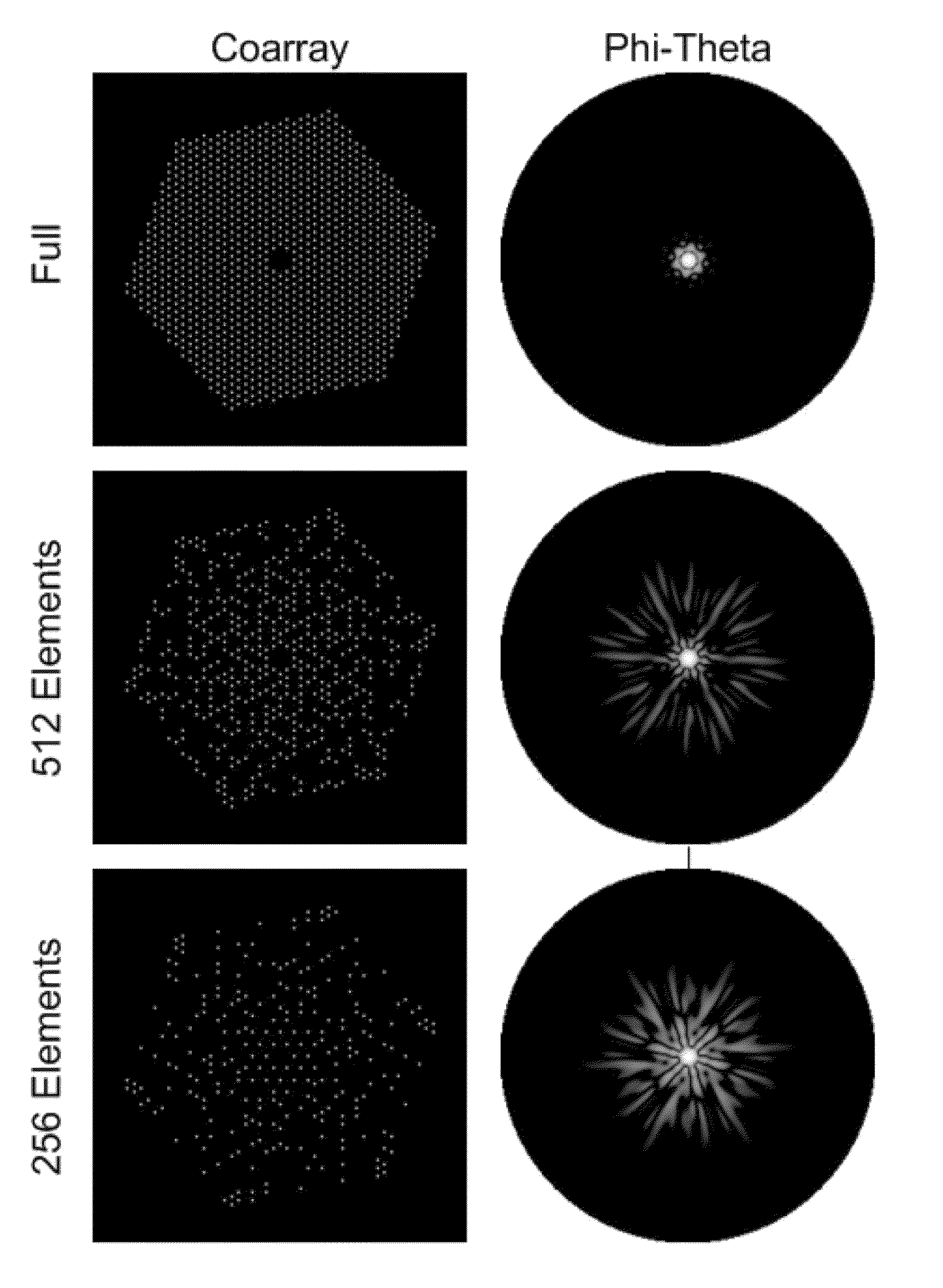
[0069]To test the imaging performance of the optimized array configurations with dual circular and hexagonal ring arrays, custom numerical simulations can be performed assuming a dual-ring array of 64 Tx and 58 Rx elements. The diameters of the Tx and Rx arrays of the dual-ring array are assumed to be 1200 μm and 1080 μm, respectively. In this case, a hexagonal dual-ring array with 12, 7-element Rx subarrays and 28 Tx subarrays was used. The dual-ring circular array has 64 Tx and 58 Rx elements.

[0070]The effectiveness of the coarray patterns of 256 and 512 firings can be compared to a full set coarray of the corresponding array configurations, i.e., 3712 firing combinations (64×58=3712). Uniformly sampled coarrays can be obtained using a nearest neighbor technique and the coarrays can be optimized using simulated annealing, as discussed above. In this example, 400 iterations and 4000 perturbations can be used to obtain an optimized set. To obtain a circularly symmetric coarray and P...


PUM


Abstract

A CMUT on CMOS imaging chip is disclosed. The imaging chip can use direct connection, CMOS architecture to minimize external connections and minimize chip cross-section. The CMOS architecture can enable substantially the entire chip area to be utilized for element placement. The chip can utilize arbitrarily selected transmit (Tx) and receive (Rx) element arrays to improve image quality, while reducing sampling time. The chip can comprise a plurality of dummy elements dispersed throughout the Tx and Rx elements to reduce cross-talk. The chip can utilize batch firing techniques to increase transmit power using sparse Tx arrays. The chip can comprise hexagonal Tx and or Rx subarrays for improved image quality with reduce sample sizes. The chip can utilize electrode geometry, bias voltage, and polarity to create phased and amplitude apodized arrays of Tx and Rx elements.

Description

CROSS-REFERENCE TO RELATED APPLICATIONS AND PRIORITY CLAIM[0001]This application claims priority under 35 U.S.C. §119(e) to, and the benefit of, U.S. Provisional Patent Application No. 61 / 485,414, entitled “Single Chip CMUT-on-CMOS Arrays for Forward-Looking Intravascular and Intracardiac Imaging,” U.S. Provisional Patent Application No. 61 / 485,417, entitled “Hexagonal Ring Arrays for Forward-Looking Intravascular and Intracardiac Imaging,” and U.S. Provisional Patent Application No. 61 / 485,423, entitled “Donut Sparse CMUT arrays for Forward-Looking Volumetric Imaging Catheter Probes,” all of which were filed 12 May 2011. The entireties of the above-mentioned applications are hereby incorporate by reference as if set forth in its entirety below.BACKGROUND OF THE INVENTION[0002]1. Field of the Invention[0003]Embodiments of the present invention relate to ultrasound imaging probes, and particularly, to flexible, single chip, CMUT based ultrasound imaging probes using various monolithi...

Claims


Application Information

Patent Timeline
IPC IPC(8): G01S15/89
CPCG01S15/89A61B8/4494A61B8/12A61B8/445B06B1/0292G01S15/8993G01S7/5208G01S15/8925G01S15/8927G01S7/52047G01S15/8913A61B8/4488G01S15/8922
Inventor DEGERTEKIN, F. LEVENTKARAMAN, MUSTAFA
Owner GEORGIA TECH RES CORP
Why Eureka
Try Eureka