Anatomic total disc replacement

a total disc and anatomic technology, applied in the field of prosthetic intervertebral discs, can solve the problems of spinal disc displacement or damage, compression or temporary deformation to a limited extent, leg pain,

Active Publication Date: 2013-05-23
CARPENTER CLYDE T
View PDF3 Cites 24 Cited by
  • Summary
  • Abstract
  • Description
  • Claims
  • Application Information

AI Technical Summary

Benefits of technology

The invention is a new spinal disc replacement that can be used after removing a diseased disc. It is flexible and strong, and acts as a shock absorber to allow spinal flexibility and movement between the vertebrae. This solves some of the problems associated with previous spinal disc prostheses.

Problems solved by technology

As a result, the gel-like nucleus can support an applied load yet can be compressed or temporarily deformed to a limited extent.
A spinal disc may be displaced or damaged due to trauma or a disease process.
A disc herniation occurs when the annulus fibers are weakened or torn and the inner material of the nucleus becomes permanently bulged, distended, or extruded out of its normal, internal annular confines The mass and / or physiologic reaction of a herniated or “slipped” nucleus tissue can compress a spinal nerve, resulting in leg pain, loss of muscle strength and control, and even paralysis.
Alternatively, with discal degeneration, the nucleus loses its water binding ability and dehydrates with consequent loss in disc height.
Consequently, the volume of the nucleus decreases, causing the annulus to buckle in areas where the laminated plies are loosely bonded.
As these overlapping plies of the annulus buckle and separate, either circumferential or radial tears may occur in the annulus, potentially resulting in persistent and disabling back pain.
Adjacent, ancillary facet joints between vertebrae bones may also be forced into an overriding position, which may cause additional back pain.
In the United States, low back pain accounts for the loss of many workdays.
Degeneration of an intervertebral disc is one of the most common causes of low back pain and therefore frequently requires treatment.
Spinal fusion has been the mainstay of surgical treatment for recalcitrant low back pain secondary to a degenerated disc, but spinal fusion causes stiffness of the vertebral segment and therefore places increased stresses on adjacent vertebral levels.
This resulted in the steel ball subsiding into the vertebral body and did not maintain disc height nor provide compressibility.
Most disc replacements of this ball and socket type of design do not allow for a mobile center of rotation in both the axial plane and the sagittal plane.
Many of these designs also lack any type of resiliently compressible material within the device to absorb compressive forces.
This may result in motion of metal on metal where the springs are attached to the endplates.
This potentially causes release of metal particulate debris into the tissues, which can stimulate foreign body reaction.
Foreign body reactions can result in resorption of adjacent bone and subsequent subsidence, loosening and pain.
Other problems with compressive spring-type prostheses are that they do not resist translational forces well and will eventually fatigue.
These devices also lack a mobile instantaneous axis of rotation.
Devices of this type present the problem of having to attach a substance of consistent elasticity to a metal end plate.
These devices do not resist shear or translational forces well.

Method used


Image

  • Anatomic total disc replacement
  • Anatomic total disc replacement
  • Anatomic total disc replacement

Examples


Embodiment Construction

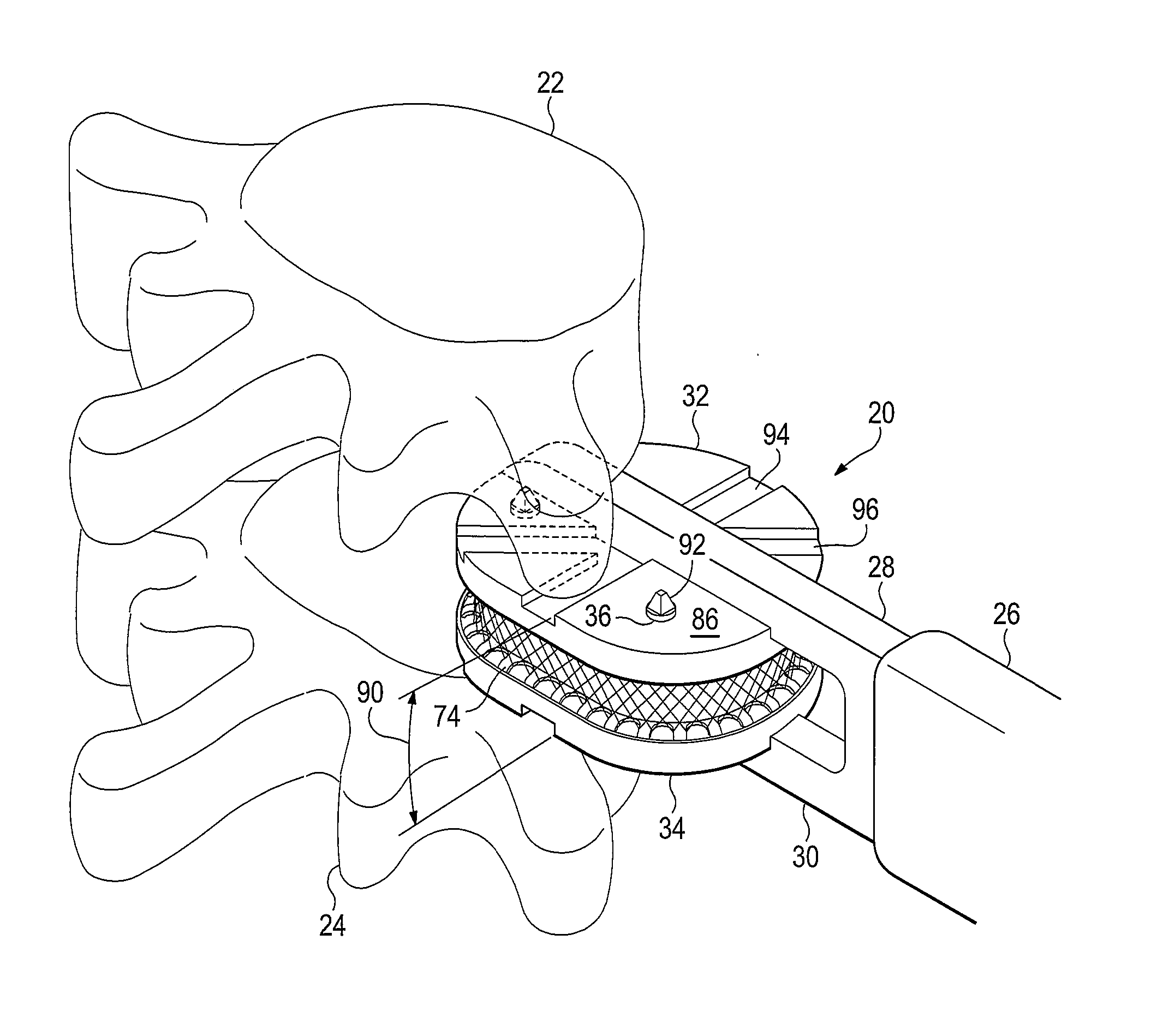
[0042]As used herein, references to certain directions and orientations such as, for example, superior (towards the head), inferior (towards the feet), lateral (towards the side), medial (towards the midline), posterior (towards the back), and anterior (towards the front refer to such directions and orientations in a standing human. As they are applied to embodiments of the invention, it will be further understood that such directions and orientations refer to the position of such embodiments within a human after implantation, when the human is standing upright.

[0043]Unless specified otherwise, a physical property designated herein for a particular embodiment will be considered to be met provided its value is within 10% of the specified value of the physical property. For example, if a value for a distance in an embodiment of the invention is specified to be 10 cm, then it will be understood that embodiments of 9 to 11 cm are within the scope of the disclosure.

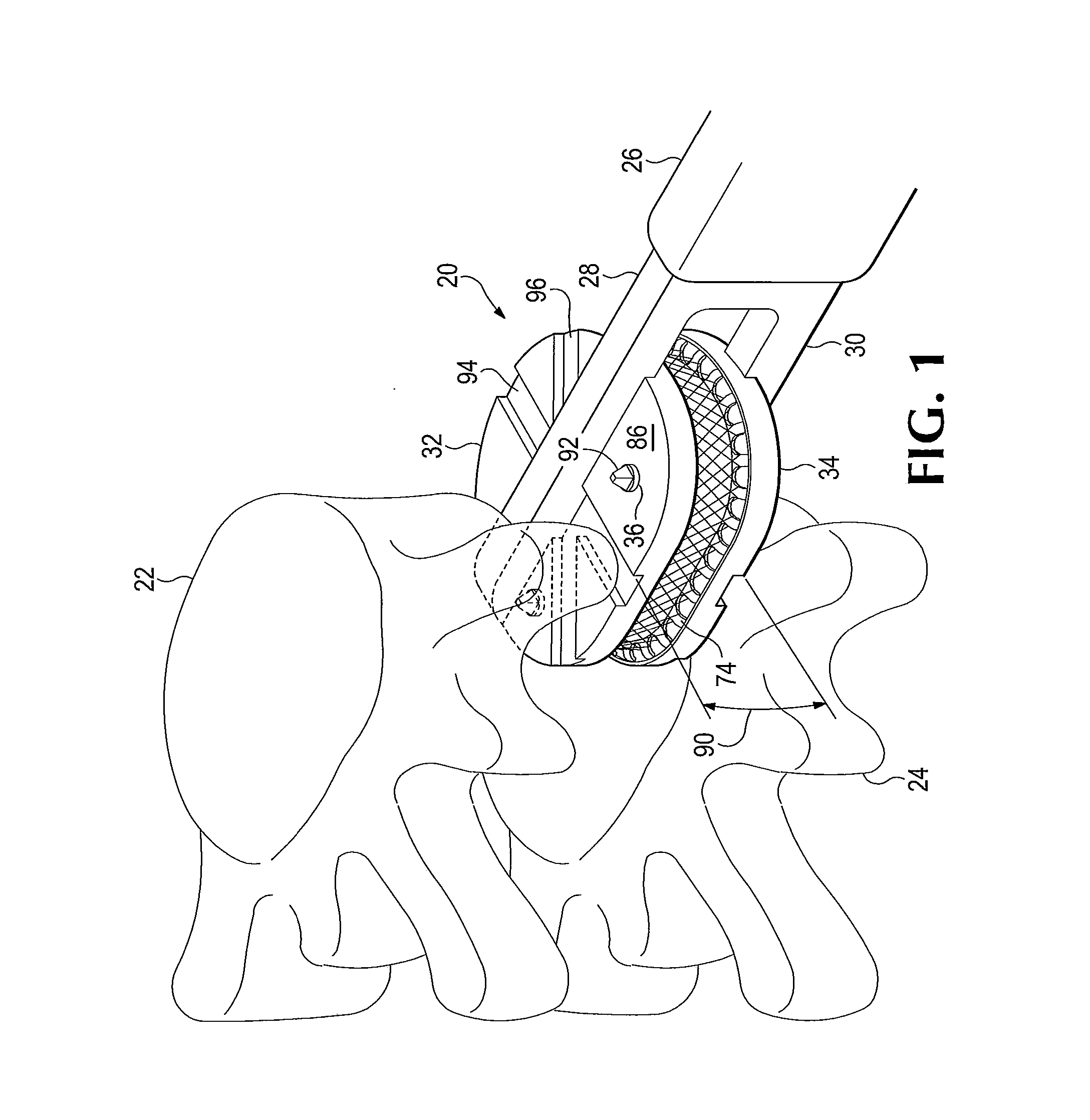
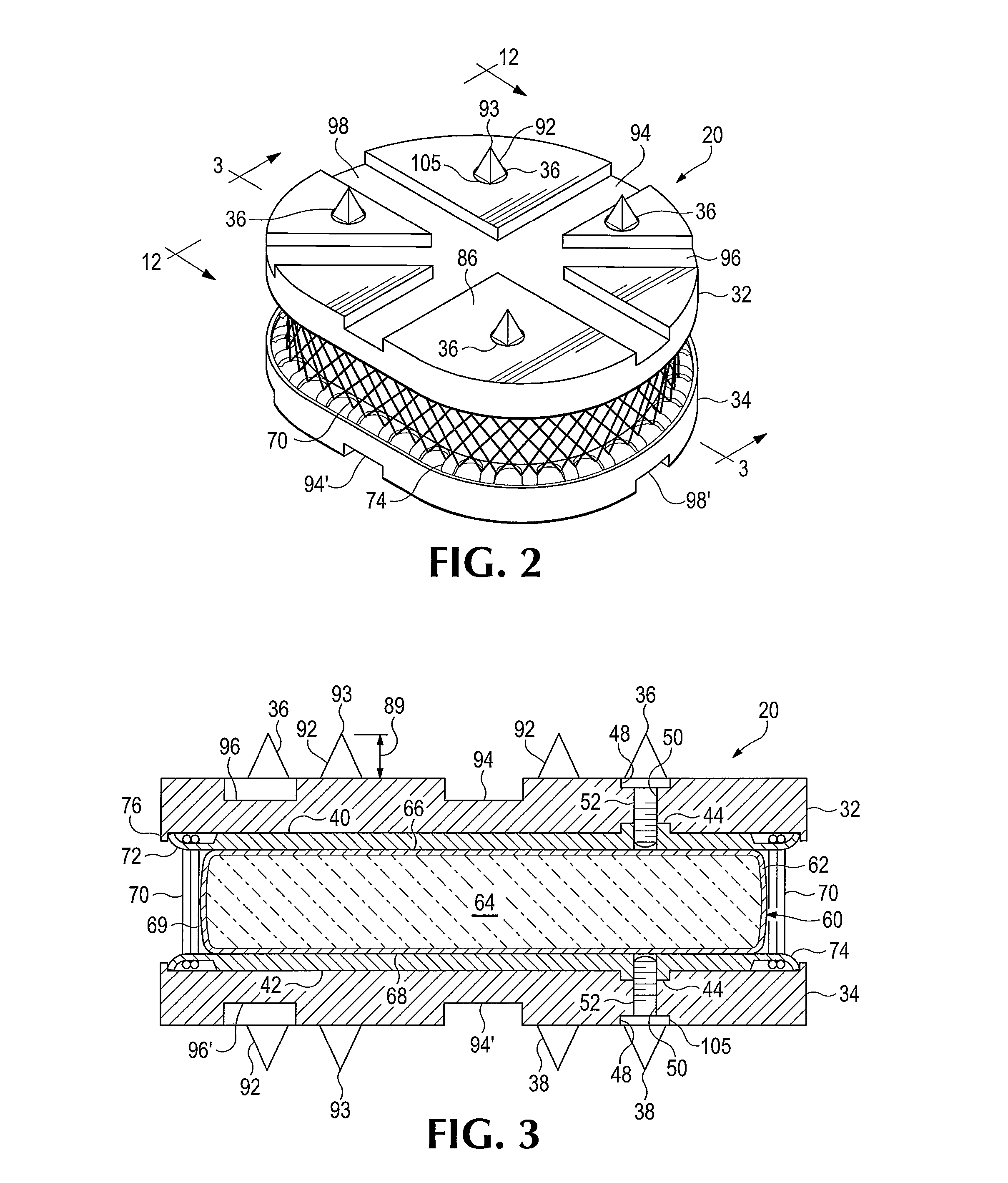
[0044]As shown in FIG....


PUM


Abstract

An artificial spinal disc prosthesis that can be implanted to replace a damaged natural spinal disc. A nucleus of compressible elastomeric material is surrounded by a winding of a slender strand of flexible tension-bearing material oriented at a pitch angle relative to a central axis. The orientation of the winding provides the prosthesis a limited amount of freedom of movement and flexibility. A pair of end caps of the prosthetic implant include angulated grooves that allow for insertion of the device between vertebral bodies from any of several directions. Special fasteners provide protruding points useful in anchoring the prosthesis.

Description

FIELD OF THE INVENTION[0001]The present invention relates to a prosthetic intervertebral disc which provides for continued mobility and which is intended to replace a diseased intervertebral disc.BACKGROUND OF THE INVENTION[0002]The vertebrate spine is made of bony structures called vertebral bodies that are separated by soft tissue structures called intervertebral discs. The intervertebral disc is commonly referred to as a spinal disc. The spinal disc serves as a mechanical cushion and a connection between the vertebral bodies, permitting controlled motions between vertebral segments of the axial skeleton. The disc acts as a synchondral joint and allows physiologic degrees of flexion, extension, lateral bending, and axial rotation of adjacent vertebral bodies relative to one another. The disc must allow these motions and yet must have sufficient elastic strength to resist the external forces and torsional moments caused by the vertebral bodies.[0003]The normal disc is a mixed avasc...

Claims


Application Information

Patent Timeline
Patent Type & Authority Applications(United States)
IPC IPC(8): A61F2/44
CPCA61F2/442A61F2310/00976A61F2002/4625A61F2/3094A61F2/4611A61F2002/2817A61F2002/2835A61F2002/30013A61F2002/30019A61F2002/30075A61F2002/30092A61F2002/30133A61F2002/30433A61F2002/30462A61F2002/30467A61F2002/30484A61F2002/30563A61F2002/30578A61F2002/30579A61F2002/30581A61F2002/30604A61F2002/30611A61F2002/30616A61F2002/30774A61F2002/30784A61F2002/30787A61F2002/3083A61F2002/30831A61F2002/30841A61F2002/30952A61F2002/4495A61F2310/00017A61F2310/00023A61F2310/00029A61F2310/00047A61F2310/00053A61F2310/00131A61F2310/00604A61F2310/00796A61F2/441A61F2002/30011
Inventor CARPENTER, CLYDE T.
Owner CARPENTER CLYDE T
Why Eureka
Try Eureka