Air fuel premixer having arrayed mixing vanes for gas turbine combustor

Active Publication Date: 2013-05-30
INNER MONGOLIA ZHONGKE PUSHI GAS TURBINE CO LTD
View PDF16 Cites 15 Cited by
  • Summary
  • Abstract
  • Description
  • Claims
  • Application Information

AI Technical Summary

Benefits of technology

[0012]In accordance with one aspect of the present invention, a fuel-air premixer for use in a combustor of a gas turbine includes an air inlet, a fuel inlet, a shroud, a central body and a cascade of vanes. The premixer mixes fuel and air in the annular mixing passage into a uniform mixture for injecting into a combustor reaction zone. The air from a compressor is injected into the mixer through an air inlet. The fuel is introduced into an air stream via fuel injection holes that pass through the walls of th

Problems solved by technology

There are several problems associated with dry low emissions combustors operating with lean premixing of fuel and air.
Specifically, there is a tendency for flammable mixture of fuel and air within the premixing section of the combustor to combust due to flashback, which occurs when flame propagates from the combustor reaction zone into the premixing section, or auto-ignition, which occurs when the dwell time and temperature of the fuel-air mixture in the premixing section are sufficient for combustion to be initiated without an igniter.
The combustion in the premixing section results in degradating of emission performance, and overheating and damaging of the premixing section.
Therefore, a problem to be solved is to prevent flashback and auto-ignition within the premixer.
In regions in the flow field in which the fuel concentration of the mixture is significantly greater than an average, the temperature of the reaction products in these regions will be higher than an average, and thus a large quantity of thermal NOx will be produced, which makes the combustor fail to meet NOx emission requirements.
In regions in the flow field in which the fuel concentration of the mixtu

Method used


Image

  • Air fuel premixer having arrayed mixing vanes for gas turbine combustor
  • Air fuel premixer having arrayed mixing vanes for gas turbine combustor
  • Air fuel premixer having arrayed mixing vanes for gas turbine combustor

Examples


Embodiment Construction

[0017]Preferred embodiments of the present invention will be described hereinafter in detail with reference to the attached drawings, wherein the like reference numerals refer to the like elements throughout the specification. These embodiments should not be construed as being limited to the embodiment set forth herein, rather for illustrative purpose.

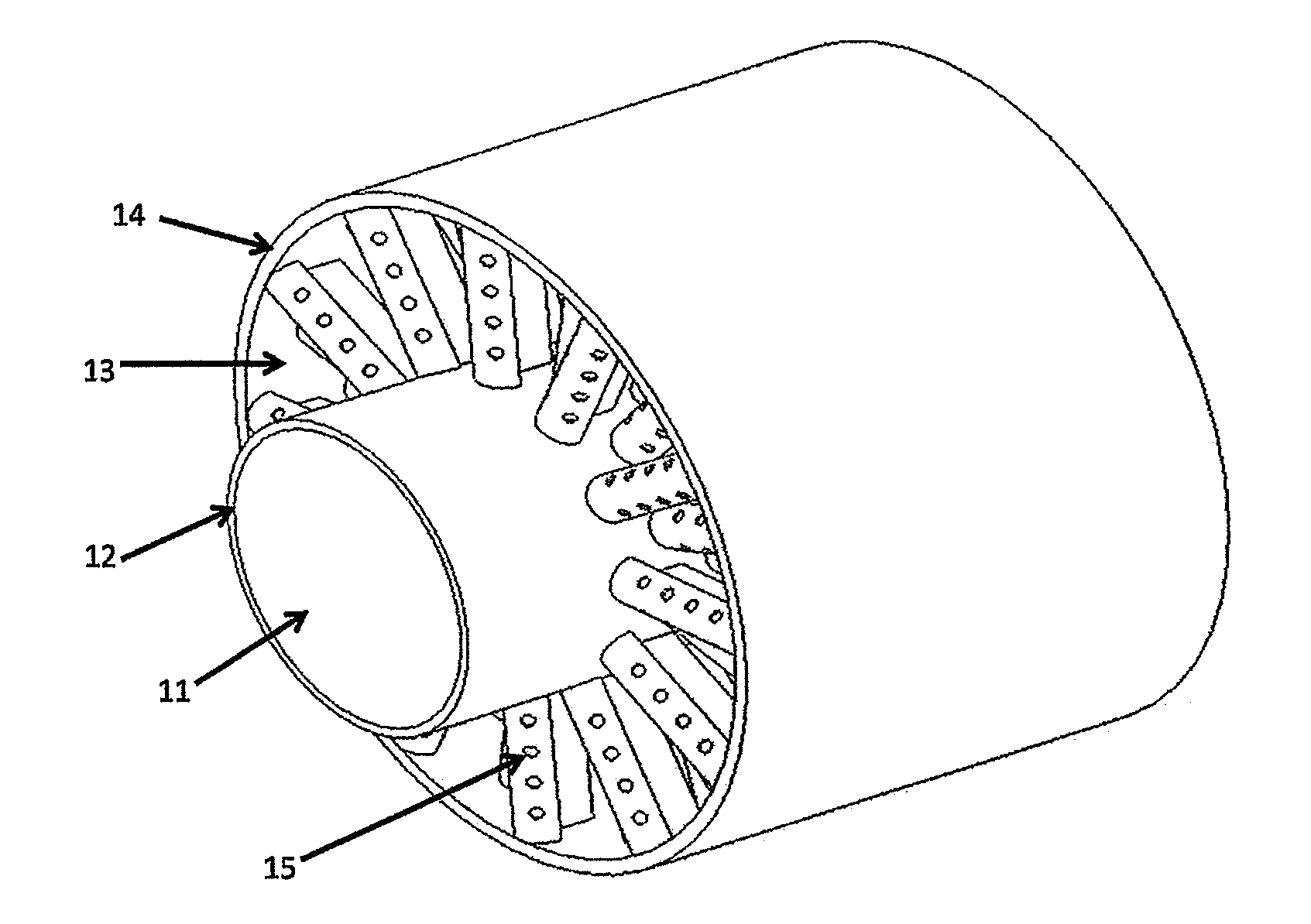
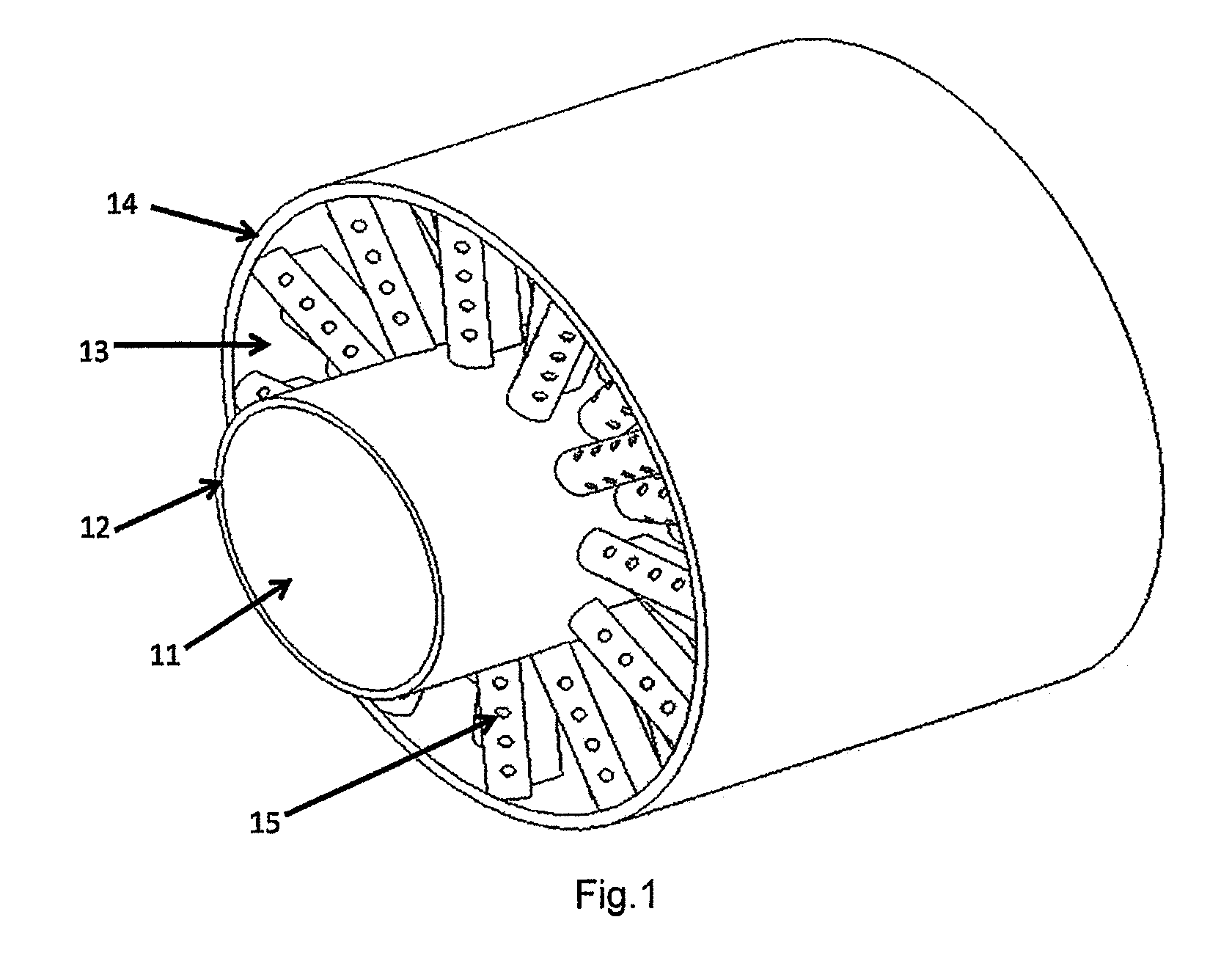
[0018]FIG. 1 shows the appearance of the premixer according to one exemplary embodiment of the invention, and FIG. 2 schematically shows the details of the shape and arrangement of the arrayed vanes.

[0019]The fuel-air premixer of the present invention for use in a combustor of a gas turbine includes an air inlet, a fuel inlet 11, a shroud 14, a central body 12 and a cascade of vanes 25,24,23. The premixer mixes fuel and air in an annular mixing passage 13 into a uniform mixture for injecting into a combustor reaction zone through the exhaust 22.

[0020]High pressure air discharged from a compressor enters the premixer through the air inl...


PUM


Abstract

A fuel-air premixer for use in a combustor of a gas turbine includes an air inlet, a fuel inlet, a shroud, a central body and a cascade of vanes. The premixer mixes fuel and air in the annular mixing passage into a uniform mixture for injecting into a combustor reaction zone. The air from a compressor is injected into the mixer through an air inlet. The fuel is introduced into air stream via fuel injection holes that pass through the walls of the vanes which contain internal fuel flow passages. The flow field inside the premixer is broken up by the arrayed vanes into a series of small regions each containing a well designed small size mixing eddy which is steadily attached to the surface of the vanes.

Description

CROSS-REFERENCE TO RELATED APPLICATION[0001]This application claims the benefit of Chinese Patent Application No. 201110380006.2 filed on Nov. 25, 2011 in the State Intellectual Property Office of China, the whole disclosure of which is incorporated herein by reference.BACKGROUND OF THE INVENTION[0002]1. Field of Invention[0003]The present invention relates to gas turbines and, in particular, to a fuel-air premixer for a combustor of a gas turbine which uniformly mixes fuel and air so as to reduce Nitrogen Oxide (NOx) formed by the combustion progress.[0004]2. Description of the Related Art[0005]The worldwide concerns of air pollution have led to stricter emission standards requiring significant reduction in gas turbine pollution emission. NOx, which is an inducement to atmospheric pollution, is generally formed in the high temperature regions of the gas turbine combustor by direct oxidation of atmospheric nitrogen with oxygen. Thus reducing the emission of NOx can be achieved by de...

Claims


Application Information

Patent Timeline
IPC IPC(8): F23R3/28
CPCF23R3/14F23R3/286F05D2240/127F05D2260/2212F23C2900/07001F23R3/18
Inventor WANG, YUEYU, ZONGMINGKONG, WENJUNWANG, BAORUIAI, YUHUA
Owner INNER MONGOLIA ZHONGKE PUSHI GAS TURBINE CO LTD
Why Eureka
Try Eureka