
Organic electroluminescence element, organic electroluminescence device, organic el display device, and organic el lighting

a technology of electroluminescence element and electroluminescence device, which is applied in the direction of di-anthraquinonyl dye, pyrene dye, anthracene dye, etc., can solve the problem of short life of the element, and achieve high luminescent efficiency, long working life, and high current efficiency

Active Publication Date: 2013-05-30
MITSUBISHI CHEM CORP
View PDF12 Cites 11 Cited by
  • Summary
  • Abstract
  • Description
  • Claims
  • Application Information

AI Technical Summary

Benefits of technology

This patent describes an organic electroluminescence element that has a long life and high luminescent efficiency. It is thought to be useful for flat-panel displays, light sources, and marker lamps. Its technical effect is to provide an organic electroluminescence element that is more stable and efficient than previous versions, making it more suitable for commercial applications.

Problems solved by technology

However, since the charge injection into the luminescent layer necessitates a large amount of energy, a high voltage is necessary for causing the organic electroluminescence element to luminesce at a high luminance.
In addition, the life of the element is short.

Method used


Image

  • Organic electroluminescence element, organic electroluminescence device, organic el display device, and organic el lighting
  • Organic electroluminescence element, organic electroluminescence device, organic el display device, and organic el lighting
  • Organic electroluminescence element, organic electroluminescence device, organic el display device, and organic el lighting

Examples


example 1

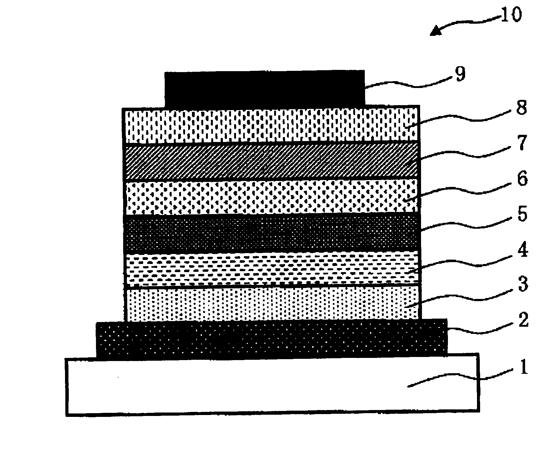
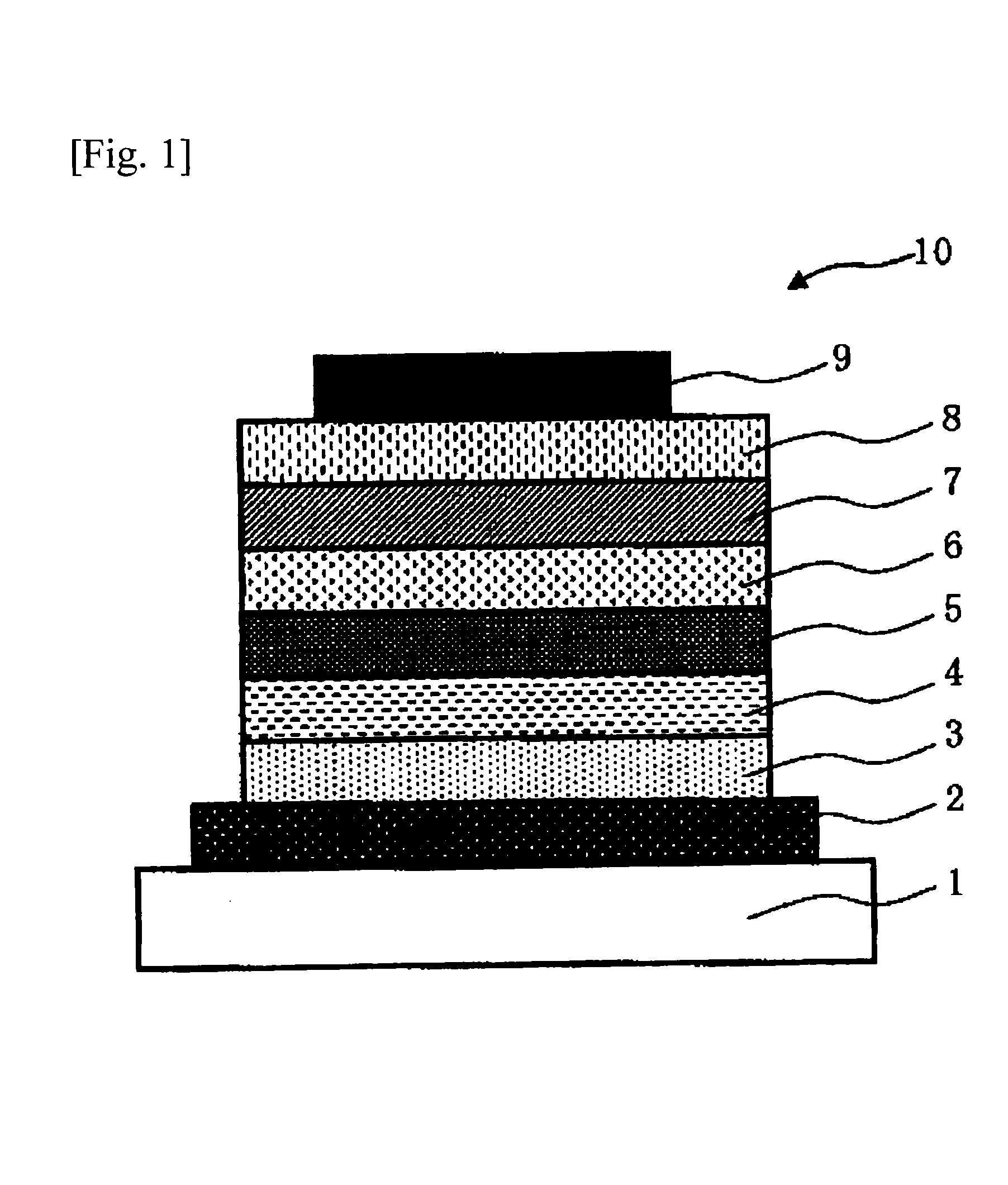
[0365]The organic electroluminescence element shown in FIG. 1 was produced.

[0366]First, a substrate obtained by depositing a transparent conductive film of ITO in a thickness of 70 nm on a glass substrate 1 and patterning the transparent conductive film into stripes having a width of 2 mm to form an ITO anode 2 (deposited by sputtering; manufactured by Sanyo Vacuum Industries Co., Ltd.) was cleaned by subjecting the substrate to ultrasonic cleaning with an aqueous surfactant solution, rinsing with ultrapure water, ultrasonic cleaning with ultrapure water, and rinsing with ultrapure water in this order, subsequently dried with compressed air, and then subjected to ultraviolet / ozone cleaning.

[0367]Next, an ethyl benzoate solution (composition for hole injection layer formation) containing 2.0% by weight the hole-transporting high-molecular compound represented by the following (P1), which had the repeating structures, and 0.8% by weight 4-isopropyl-4′-methyldiphenyliodonium tetrakis(p...

example 2

[0389]An organic electroluminescence element was produced by the same method as in Example 1, except that the electron transport material (eH-2) shown below was used in the luminescent layer in place of the electron transport material (eH-1) used in Example 1. This element was evaluated in the same manner as in Example 1. The results thereof are summarized in Tables 3 and 4 together with the value of |EA1|−|EA2| and the value of |WF|−|EA3|.

example 3

[0390]An organic electroluminescence element was produced by the same method as in Example 1, except that the electron transport material (eH-5) shown below was used in the hole blocking layer in place of the electron transport material (eH-1) used in Example 1. This element was evaluated in the same manner as in Example 1. The results thereof are summarized in Tables 3 and 4 together with the value of |EA1|−|EA2| and the value of |WF|−|EA3|.


PUM


Abstract

The present invention relates to an organic electroluminescence element which comprises an anode, a luminescent layer, two or more electron transport layers and a cathode, in this order, wherein at least one of the two or more electron transport layers adjoins the luminescent layer, the luminescent layer contains a luminescent material and a charge transport material, the electron transport layer which adjoins the luminescent layer contains a charge transport material, the charge transport material contained in the luminescent layer and the charge transport material contained in the electron transport layer which adjoins the luminescent layer may be the same material or may be different material, and the specific electron affinities EA1, EA2 and EA3, and the specific work function WF satisfy the specific relationship.

Description

TECHNICAL FIELD[0001]The present invention relates to an organic electroluminescence element and an organic electroluminescence device, an organic EL display device, and an organic EL lighting which each include the element.BACKGROUND ART[0002]Organic electroluminescence elements are being developed enthusiastically in order to use the elements in applications such as displays and lightings. An organic electroluminescence element is usually configured at least of a pair of electrodes and an organic luminescent layer interposed therebetween. The organic electroluminescence element emits light usually by the following mechanism. An electric field is applied between the electrodes and, as a result, electrons and holes are injected respectively from the cathode and the anode into the luminescent layer, where the electrons recombine with the holes to yield excitons, which cause the element to emit light.[0003]However, since the charge injection into the luminescent layer necessitates a l...

Claims


Application Information

Patent Timeline
Patent Type & Authority Applications(United States)
IPC IPC(8): H01L51/52
CPCH01L51/0067H01L51/0072H01L51/5004H01L51/5048H01L51/52C09B1/005C09B47/045C09B57/00C09B57/001C09B1/00C09B47/00H10K85/654H10K85/6572H10K50/11H10K2101/40H10K50/14H10K50/80
Inventor TANAKA, FUTOSHIOKABE, KAZUKITAKAHASHI, ATSUSHI
Owner MITSUBISHI CHEM CORP
Learn More