
Engine generator

a generator and engine technology, applied in the direction of engines, machines/engines, mechanical equipment, etc., can solve the problems of inability to re-energize the engine, failure to detect the weakness of the battery, and considerable time-consuming to recharg

Inactive Publication Date: 2013-05-30
KAWASAKI HEAVY IND LTD
View PDF11 Cites 15 Cited by
  • Summary
  • Abstract
  • Description
  • Claims
  • Application Information

AI Technical Summary

Benefits of technology

The engine generator described in this patent does not require a large air compressor or a separate reservoir of compressed air to drive it. Instead, it uses unburnable gas from a gas container, which reduces installation space and manufacturing costs, and also reduces running costs. A valve control system ensures that the air motor can be driven reliably to power the engine. In addition, the engine generator can be used with commercially available gas containers, allowing for easy replacement. The use of multiple container units containing a certain amount of gas for one-time driving of the engine further increases the flexibility and reliability of the system. Overall, this design reduces installation and maintenance costs, and makes the engine generator more suitable for use in fire extinguishing facilities.

Problems solved by technology

Typically, the recharge takes considerable time.
This means that, if another outage would occur during the recharge, it may be impossible to re-energize the engine.
Further, weakness of battery should always be detected.
Furthermore, the disposal of exhausted batteries results in environmental pollution.
Using air motor needs an air compressor and a high-pressure reservoir, which requires a large space for their installation and their installation works.
Further, a drain chamber is needed for removing lubricant oil from the drive source of the air compressor and the compressed air generated by the air compressor, which increases the installation cost and causes additional costs for maintenance of the drain chamber and for disposal of the lubricant collected at the drain chamber.
However, a considerable time is required to fill the tank with the pressurized air.

Method used


Image

  • Engine generator
  • Engine generator
  • Engine generator

Examples


Embodiment Construction

[0020]With reference to the accompanying drawings, preferred embodiments of the invention will be described below. Like reference numbers denote like or similar parts throughout the specification.

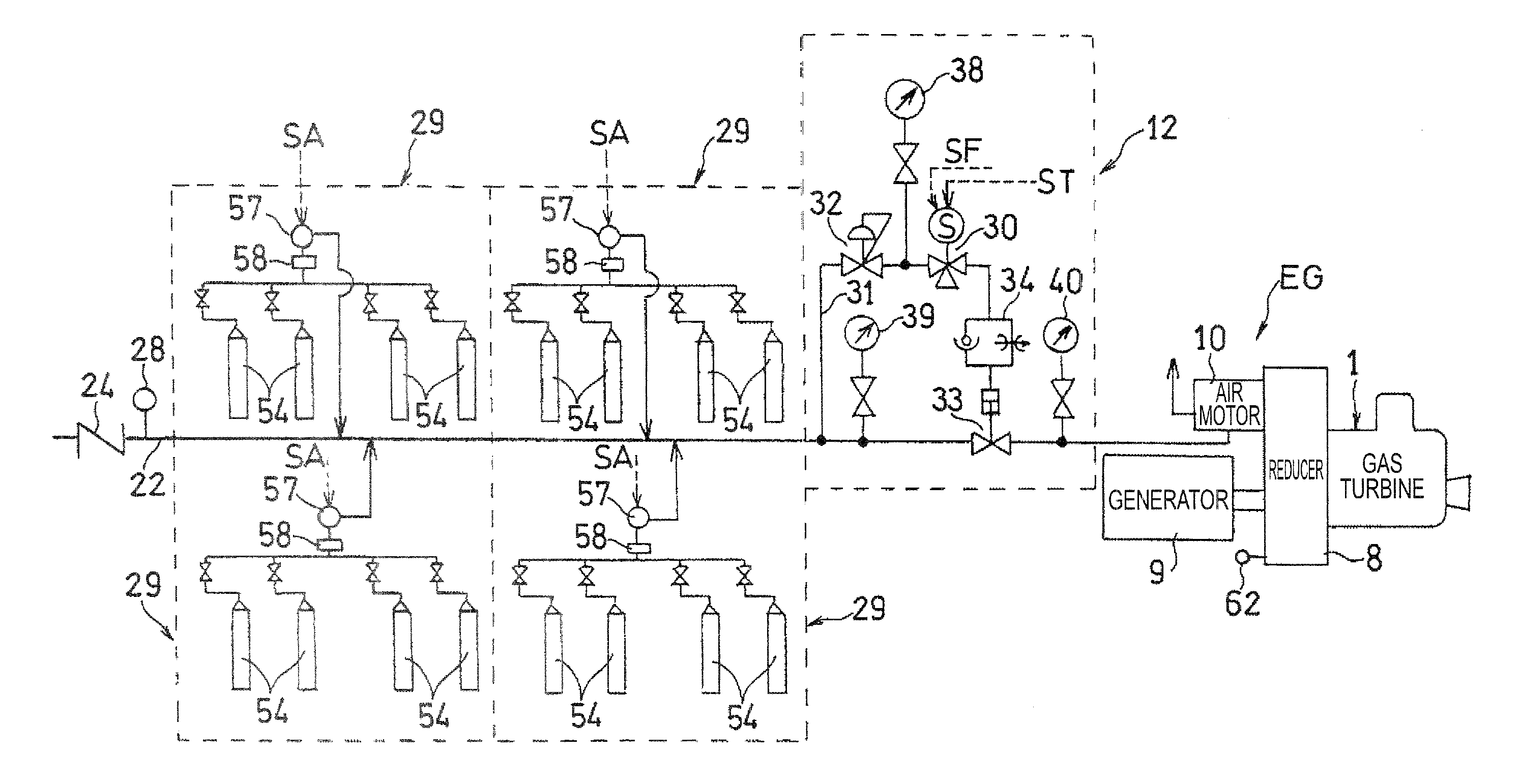
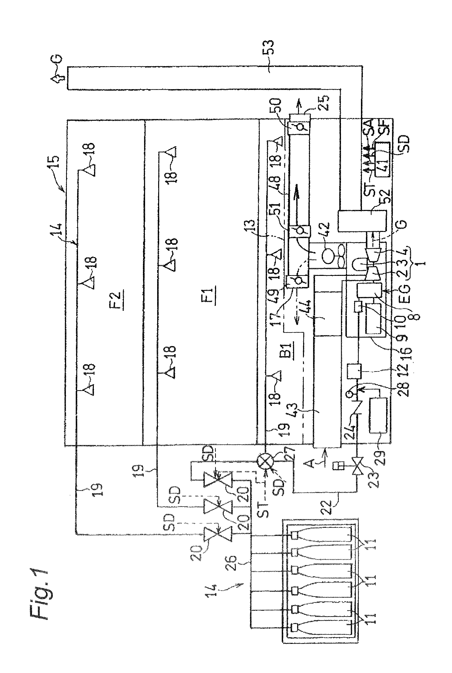
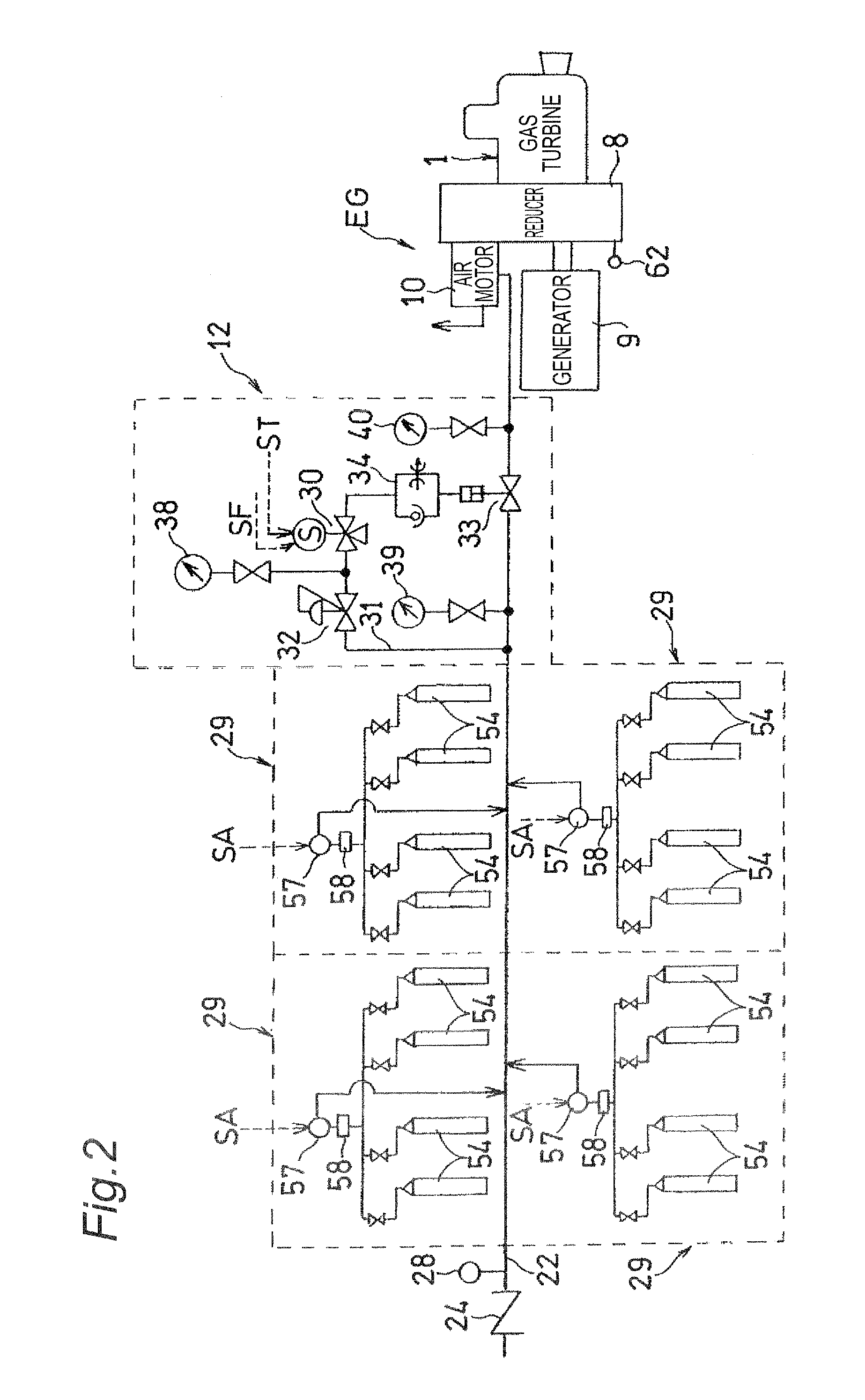
[0021]FIG. 1 shows an emergency gas turbine generator, generally indicated at EG, according to the invention and a fire extinguishing facility generally indicated at 14. According to the embodiment, the generator EG is a gas turbine generator. The gas turbine generator EG is installed within a generator room 13 in the first the basement B1, for example, of the building 15 or business facility. A gas turbine engine 1 is provided which comprises major components such as a compressor 2, combustors 3 and a turbine 4 and is connected through a reducer 8 to a generator 9. The fire extinguishing facility 14 is extended throughout the building 15. In the embodiment, several equipments of the facility 14 are disposed in the first basement B1, the first floor F1 and the second floor F2.

[0022]The gas ...


PUM


Abstract

An engine generator for driving an air motor to energize an engine is provided which reduces an installation space and facility and running costs. The engine generator (EG) is attached to a fire extinguishing facility (14). The fire extinguishing facility is designed to eject unburnable gas supplied from gas containers (11) and comprises an air motor (10) for driving an engine, and a valve unit (12) designed to drive in response to an instruction signal, control a pressure of the unburnable gas from the gas container and supply the pressure controlled unburnable gas to the air motor (10).

Description

TECHNICAL FIELD[0001]The present invention relates to an engine generator. In particular, the present invention relates to an emergency engine generator in which an air motor is driven to energize a drive source or engine for generating electric power in case of power outage or disaster.BACKGROUND OF THE INVENTION[0002]Conventionally, an electric motor or air motor is used as a starter for the emergency engine generator. For example, the electric motor is used for the starter of the emergency generator equipped with a liquid-fuel engine because a gas-fuel supply from town gas facilities can be disconnected in case of disasters such as earthquakes. The air motor, on the other hand, is used for the starter of the emergency generator with a gas turbine engine which drives using energy obtained by combusting gaseous fuel because an internal spark in the electric motor can ignite leaked gas.[0003]Accordingly, as described in JP 6-173715 A, the conventional air motor starter is designed s...

Claims


Application Information

Patent Timeline
IPC IPC(8): F02N7/08
CPCF01D15/00F02C7/27F02N7/08F05D2210/12A62C35/58F02C7/272
Inventor WATANABE, TAKATOSHITANAKA, KATSUNORIKOBAYASHI, HIROTAKE
Owner KAWASAKI HEAVY IND LTD
Learn More