Low bend loss optical fiber

a technology of optical fibers and low bend loss, which is applied in the direction of optical fibers with graded refractive index core/cladding, optical waveguide light guides, instruments, etc., can solve the problems of increased manufacturing cost, increased manufacturing cost, and increased manufacturing cost, so as to achieve low bend loss and macrobend performance. , the index in the second inner cladding region is reduced, and the performance is good

Active Publication Date: 2013-05-30
CORNING INC +1
View PDF7 Cites 21 Cited by
  • Summary
  • Abstract
  • Description
  • Claims
  • Application Information

AI Technical Summary

Benefits of technology

[0013]Applicants discovered having a fiber with a trench that has a non-constant relative refractive index delta helps in achieving good macrobending performance at both small (<10 mm) and large (>20 mm) diameters. The following single mode fiber embodiments have an offset trench with a non-constant relative refractive index delta that decreases with an increasing radius in at least a region thereof, resulting in low macrobend loss and opticals (optical performance parameters) that are ITU-G.652 standards compliant. In at least some embodiments the index in the second inner cladding region decreases with increasing radial position.

Problems solved by technology

It has been difficult in some single mode optical fiber designs to achieve both low bend loss at both large and small bends at the same time.
In these designs, while the performance of the fiber at smaller diameters (˜10 mm mandrel diameter) is excellent (<0.25 dB / turn), the performance at large diameters (˜30 mm mandrel diameter) is not as good as in other bend optimized fibers that have been optimized for larger bend diameters.
However, such an approach results in additional steps during processing and makes making of the fiber more costly.

Method used


Image

  • Low bend loss optical fiber
  • Low bend loss optical fiber
  • Low bend loss optical fiber

Examples


examples 1-6

FIBER EXAMPLES 1-6

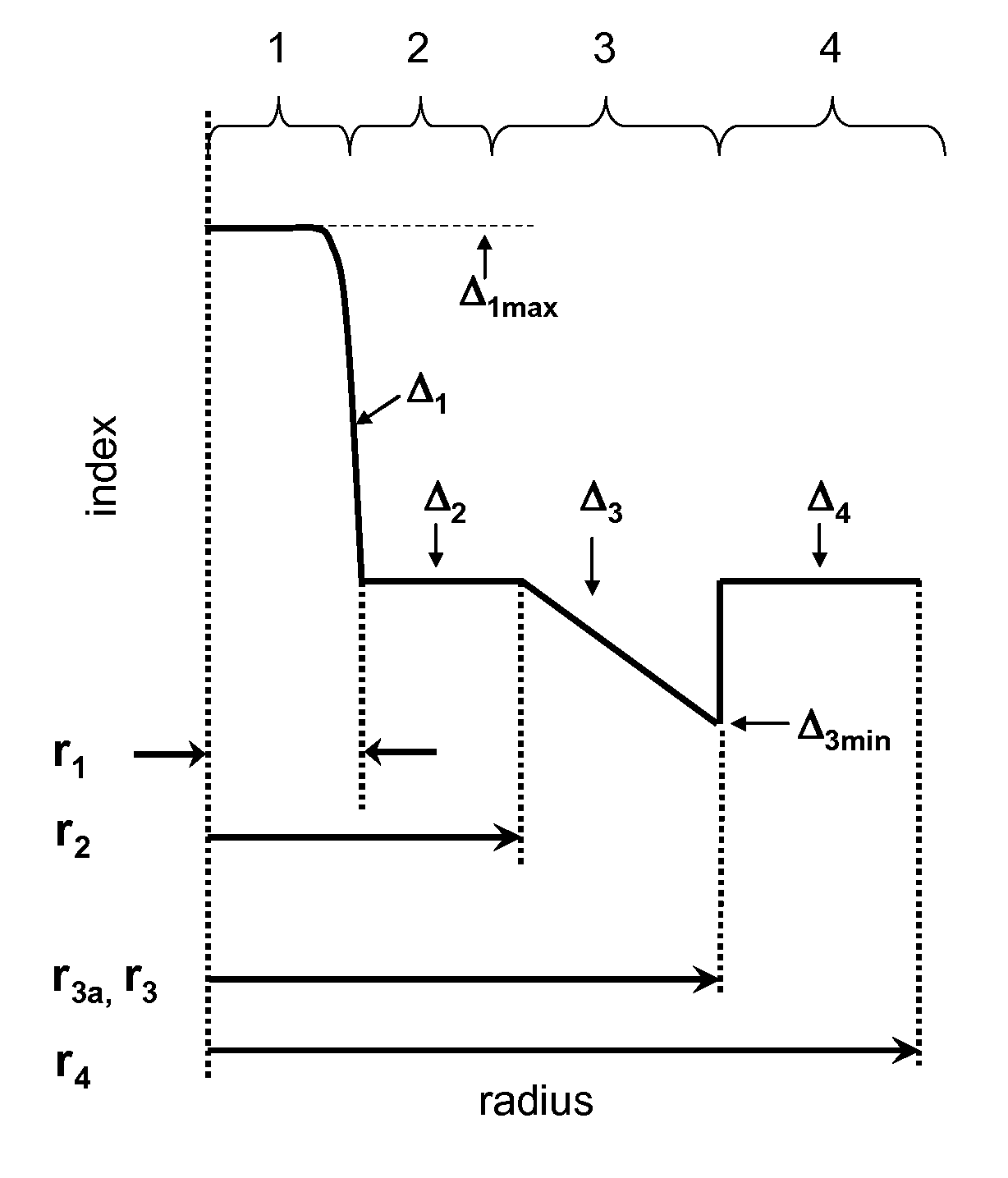
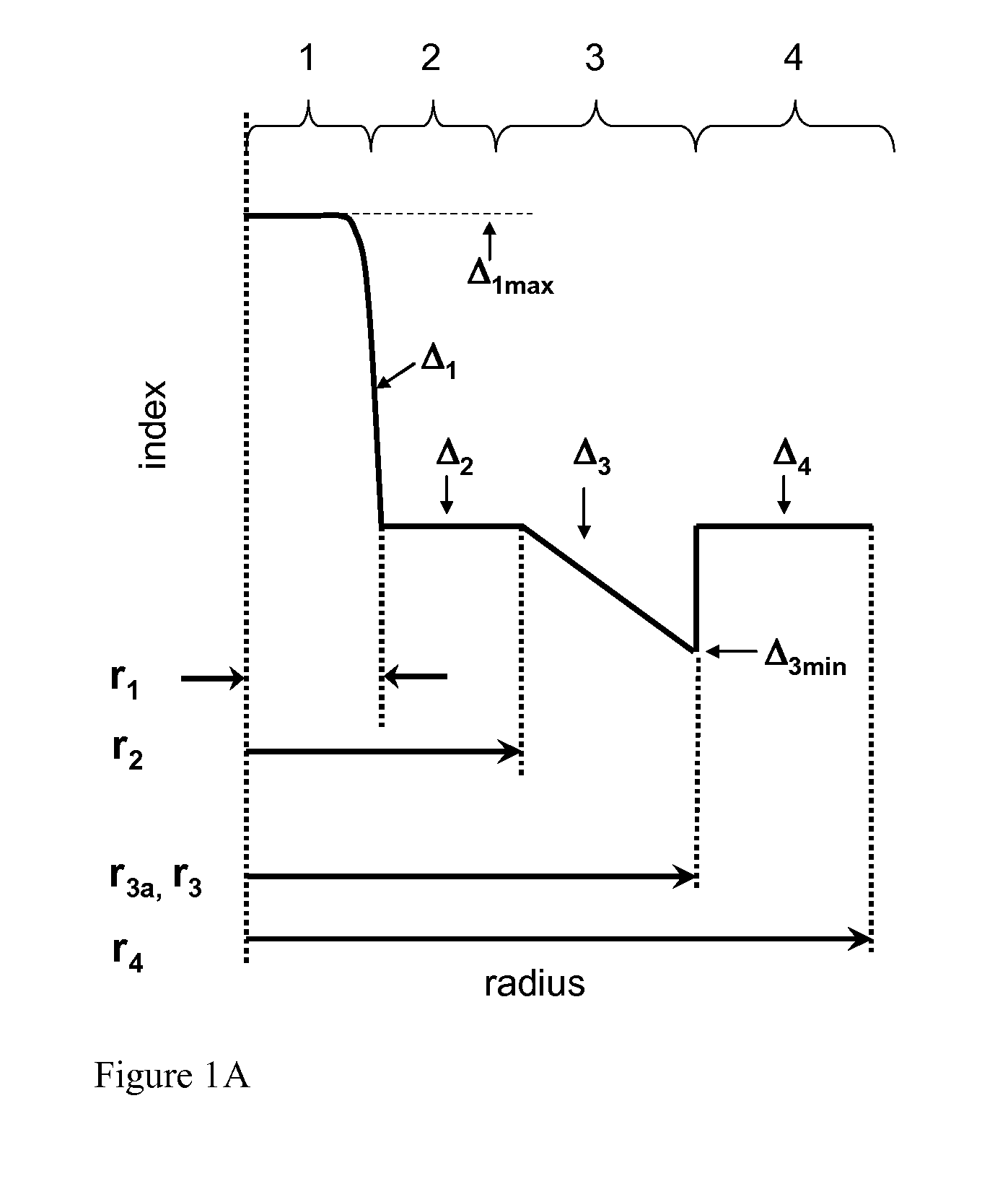
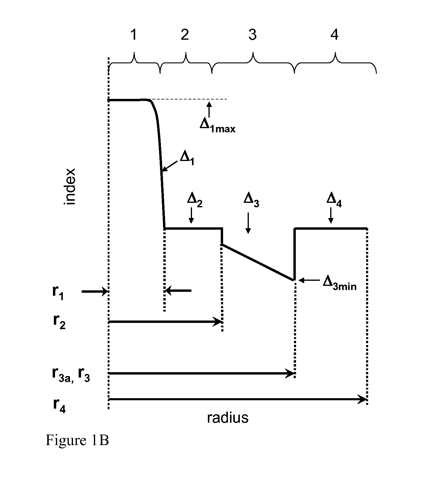
[0062]Tables 1A, 1B, 2A, 2B, 3-5 below list characteristics of modeled illustrative examples 1-6 and 8-27, manufactured fiber example 7, and those of the two comparative example fibers. In particular, set forth below for each example of Table 1A and 1B is the relative refractive index delta Δ1, alpha, and outer radius r1 of the central core region 1, relative refractive index delta Δ2 and outer radius r2 first inner cladding region 2, relative refractive index delta Δ3 and volume V3 of the second inner cladding region 3, relative refractive index delta Δ4 and volume V4 of the outer cladding region 4, which is calculated between inner radius r3 of outer cladding region 3 and a radial distance of 30 microns, and a moat volume ratio.

TABLE 1AComparativeExemplaryExemplaryExemplaryExampleembodimentembodimentembodimentParameter1123Δ1max (%)0.350.350.350.39α2020202r1 (microns)4.04.04.05.4Δ2 (%)0.000.000.000.00r2 (microns)9.57.67.66.6Δ3 (%)−0.28−0.40−0.40−0.40r3 (microns)16...


PUM


Abstract

According to some embodiments a single mode fiber includes:a germania doped central core region having outer radius r1 and relative refractive index Δ1; anda cladding region comprising (i) a first inner cladding region having an outer radius r2>6 microns and relative refractive index Δ2 and 0.3≦r1 / r2≦0.85; and (ii) a second inner cladding region having an outer radius r3>9 microns and comprising a minimum relative refractive index Δ3, wherein said second inner cladding region has at least one region with a relative refractive index delta that becomes more negative with increasing radius; and (iii) an outer cladding region surrounding the inner cladding region and comprising relative refractive index Δ4, wherein Δ1>Δ2>Δ3, Δ3<Δ4.

Description

CROSS-REFERENCE TO RELATED APPLICATIONS[0001]This application claims the benefit of priority under 35 U.S.C. §119 of U.S. Provisional Application Ser. No. 61 / 564902 filed on Nov. 30, 2011 the content of which is relied upon and incorporated herein by reference in its entirety.FIELD[0002]The present invention relates to optical fibers having low bend losses.TECHNICAL BACKGROUND[0003]There is a need for low bend loss optical fibers, particularly for optical fibers utilized in so-called “access” and fiber to the premises (FTTx) optical networks. Optical fiber can be deployed in such networks in a manner which induces bend losses in optical signals transmitted through the optical fiber. Some fiber applications that can impose physical demands such as tight bend radii, or compression of optical fiber, etc., that induce fiber bend losses. The requirements that impose these demands include, for example, the deployment of optical fiber in optical drop cable assemblies, distribution cables w...

Claims


Application Information

Patent Timeline
Patent Type & Authority Applications(United States)
IPC IPC(8): G02B6/028
CPCG02B6/028G02B6/0286G02B6/0365G02B6/03638G02B6/03627G02B6/03633
Inventor BERKEY, GEORGE EDWARDBOOKBINDER, DANA CRAIGDAWES, STEVEN BRUCELI, MING-JUNTANDON, PUSHKARWANG, JI
Owner CORNING INC
Why Eureka
Try Eureka