
Drill and method of manufacturing machined product

Active Publication Date: 2013-05-30
SUBARU CORP +1
View PDF24 Cites 17 Cited by
  • Summary
  • Abstract
  • Description
  • Claims
  • Application Information

AI Technical Summary

Benefits of technology

The present invention provides a drill with excellent chip-discharging performance. The drill has a unique design that allows chip produced from the cutting edges to smoothly pass through the flute, resulting in improved discharging performance. Additionally, the drill can be used without the need for a prepared hole, reducing production costs and avoiding quality variations. Overall, the drill improves efficiency and productivity in hole working operations.

Problems solved by technology

However, a conventional step drill described in JP 2007-7831 A has a problem that discharging performance of chip is inferior.
Hence, if a through hole is formed using the conventional step drill, the through hole is prone to be clogged with produced chip, and there is a problem that an inner wall surface of the through hole is damaged or a cutting edge becomes fractured.

Method used


Image

  • Drill and method of manufacturing machined product
  • Drill and method of manufacturing machined product
  • Drill and method of manufacturing machined product

Examples


Embodiment Construction

[0019]

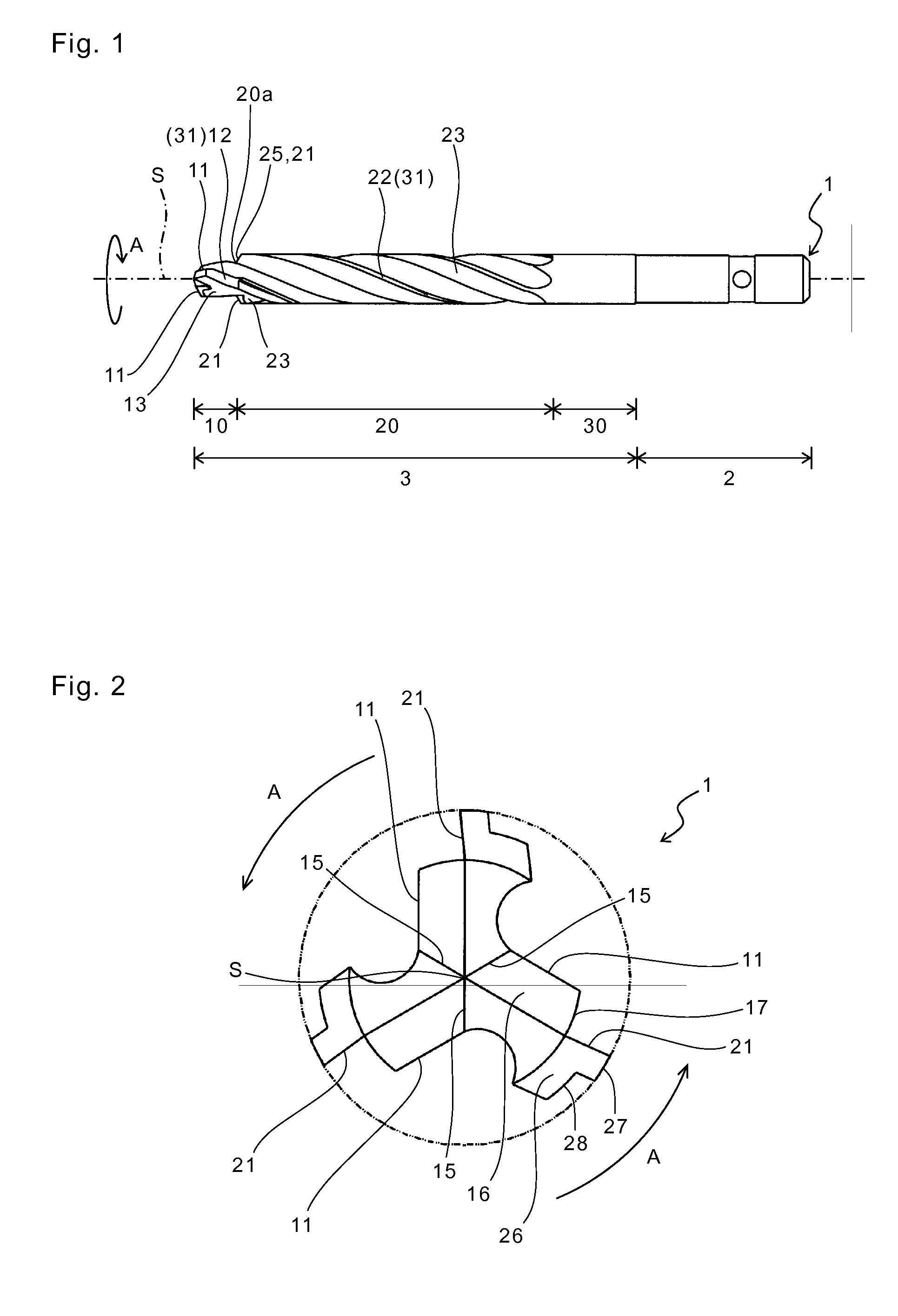
[0020]A drill according to an embodiment of the present invention will be described in detail using FIGS. 1 to 4.

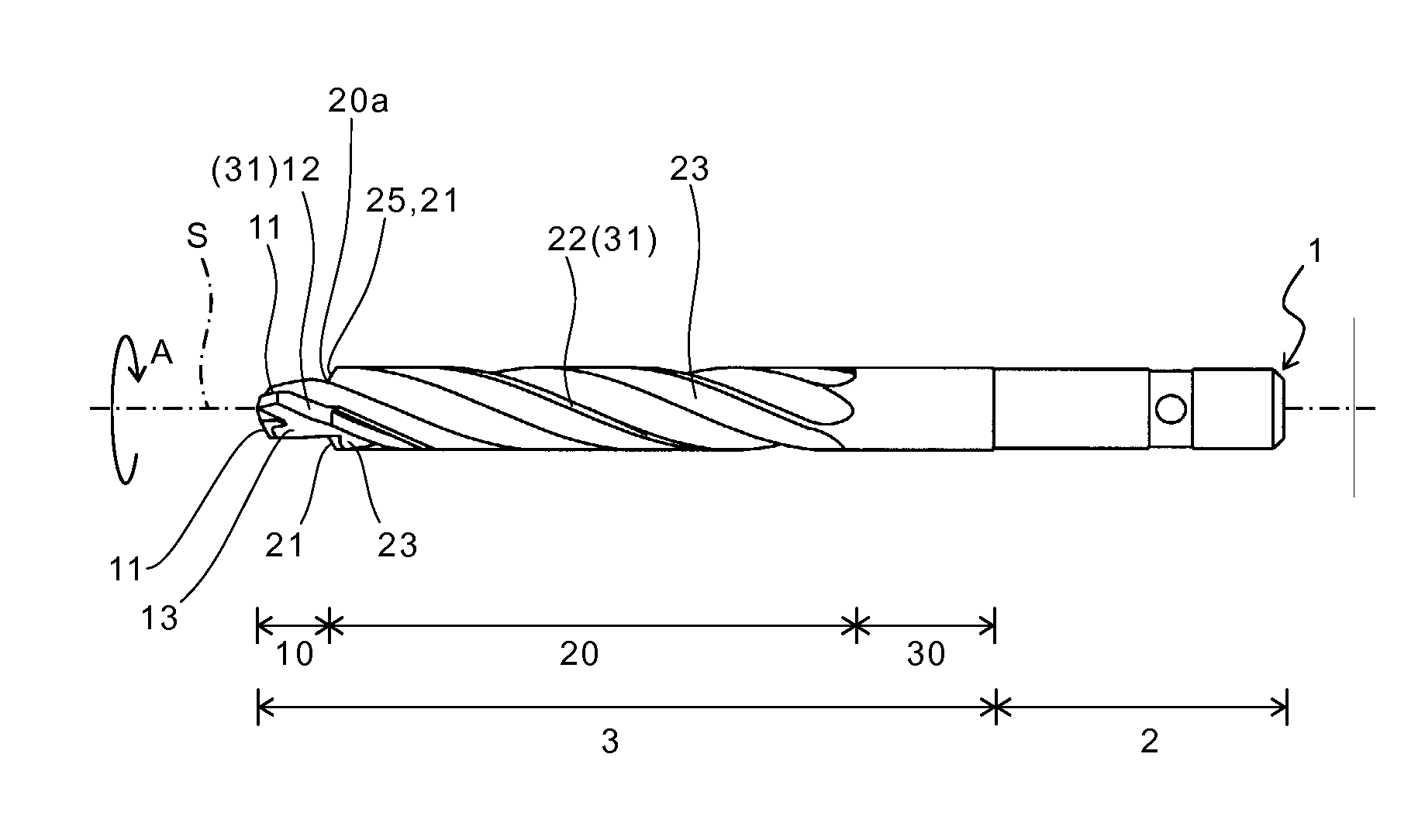
[0021]As shown in FIG. 1, a drill 1 of the embodiment can rotate around a rotation axis S in a direction of an arrow A, and includes a shank portion 2 and a cutting portion 3 in this order from its base end.

[0022]The shank portion 2 is grasped by a rotation shaft of a machine tool, and is located at the base end of the drill 1. Examples of the machine tool which grasps the shank portion 2 are a hand drill and a machining center, and especially the hand drill is preferable.

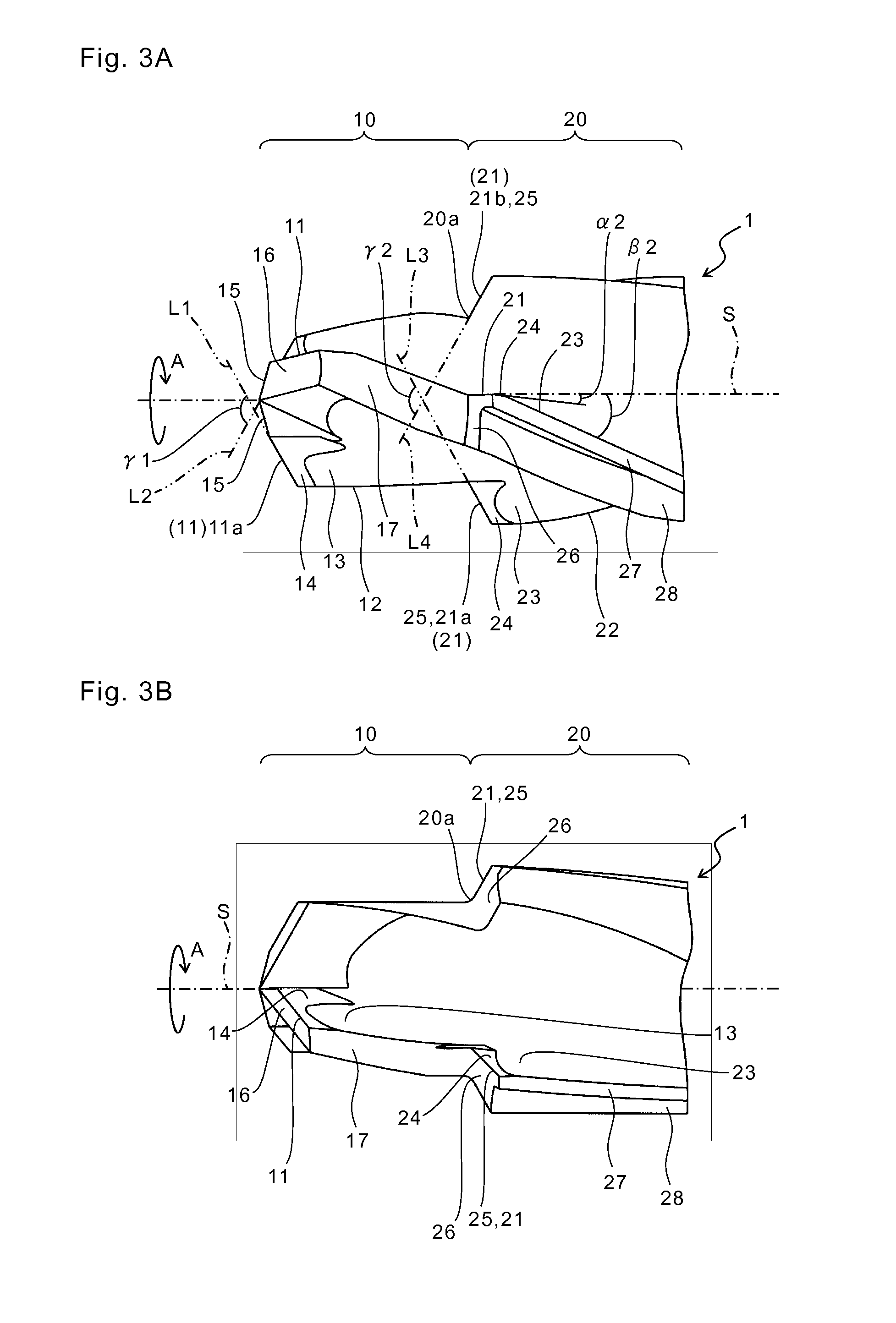
[0023]The cutting portion 3 comes into contact with a workpiece, and is located on a side of one end of the shank portion 2. The cutting portion 3 of the embodiment is substantially cylindrical in shape, and includes a first region 10 located at a front end portion of the drill 1, and a second region 20 which is continuous with the first region 10.

[0024]The first region 10 includes a plurality of f...


PUM

PropertyMeasurementUnit
Lengthaaaaaaaaaa
Angleaaaaaaaaaa
Diameteraaaaaaaaaa

Abstract

A drill includes a substantially cylindrical cutting portion includes a first region located at a front end portion, and a second region which has a step whose diameter increases as going from the first region to a rear end in a sectional view perpendicular to a rotation axis, and which is continuous with the first region in an end of the second region on a side of the step, and using this drill, a method of manufacturing a machined product is provided.

Description

CROSS-REFERENCE TO RELATED APPLICATIONS[0001]The present application claims priority under 35 U.S.C. §119 to Japanese Patent Application No. 2011-262668, filed Nov. 30, 2011, the content of the application is incorporated herein by reference in their entirety.BACKGROUND OF THE INVENTION[0002](1) Field of the Invention[0003]The present invention relates to a drill and a method of manufacturing a machined product.[0004](2) Description of Related Art[0005]As a drill capable of forming, at a time, a stepped hole in which a diameter is varied in midstream and a chamfered hole whose opening is chamfered, a step drill is known (see JP 2007-7831 A for example).[0006]However, a conventional step drill described in JP 2007-7831 A has a problem that discharging performance of chip is inferior. Hence, if a through hole is formed using the conventional step drill, the through hole is prone to be clogged with produced chip, and there is a problem that an inner wall surface of the through hole is ...

Claims


Application Information

Patent Timeline
IPC IPC(8): B23B51/00B23B35/00
CPCB23B51/009B23B35/00Y10T408/906B23B2251/04Y10T408/03B23B2228/36B23B2251/48B23B51/02B23B51/0411
Inventor ONO, YUZURUKOIKE, YOSHIFUMIKATAOKA, HIDEAKI
Owner SUBARU CORP
Learn More