Metallic bondcoat or alloy with a high gamma/gamma' transition temperature and a component

Active Publication Date: 2013-05-30
SIEMENS AG
View PDF0 Cites 1 Cited by
  • Summary
  • Abstract
  • Description
  • Claims
  • Application Information

AI Technical Summary

Benefits of technology

[0006]The problem is solved by a metallic coating or an alloy a

Problems solved by technology

These materials are optimized for strength and are not able to withstand oxidation and/or corrosion attack at higher temperatures.
With increasing bondcoat temperatures

Method used


Image

  • Metallic bondcoat or alloy with a high gamma/gamma' transition temperature and a component
  • Metallic bondcoat or alloy with a high gamma/gamma' transition temperature and a component
  • Metallic bondcoat or alloy with a high gamma/gamma' transition temperature and a component

Examples


Example

[0013]The figures and the description are only embodiments of the invention.

DETAILED DESCRIPTION OF INVENTION

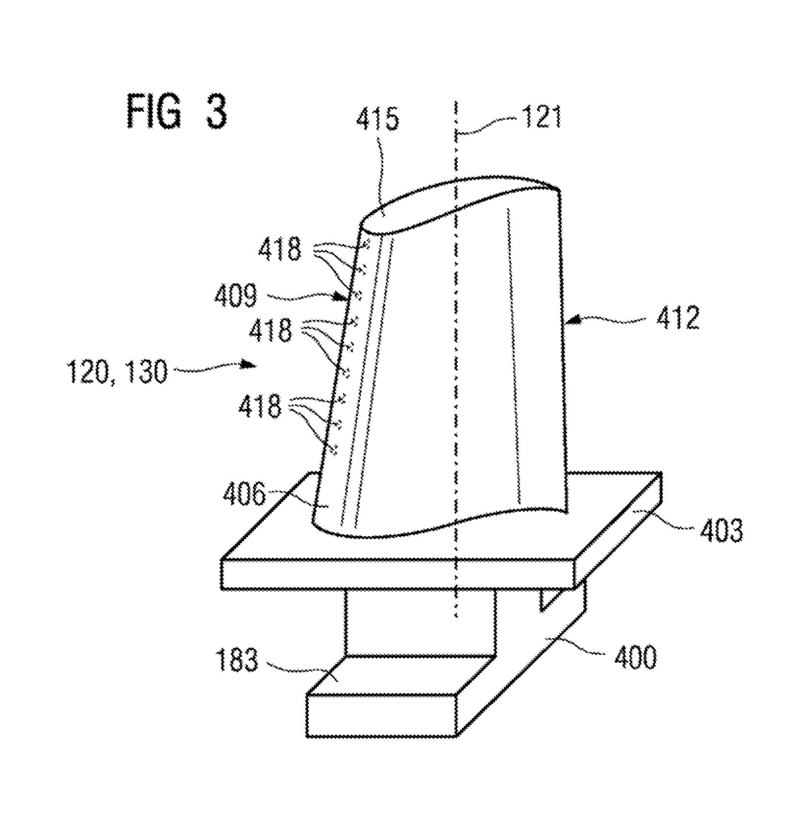
[0014]FIG. 3 shows a perspective view of a rotor blade 120 or guide vane 130 of a turbomachine, which extends along a longitudinal axis 121.

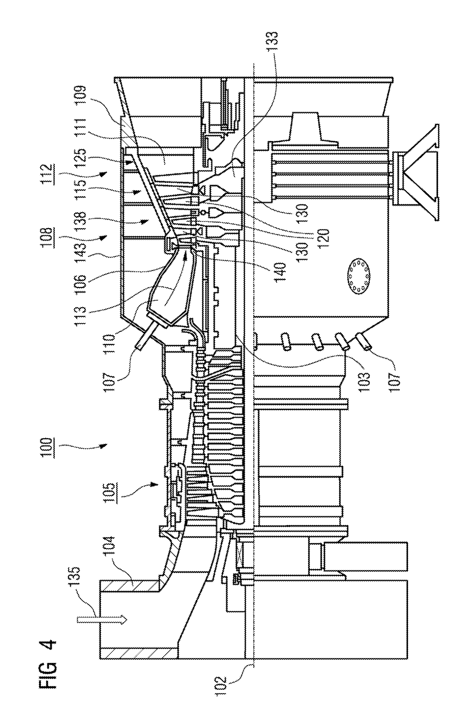
[0015]The turbomachine may be a gas turbine of an aircraft or of a power plant for generating electricity, a steam turbine or a compressor.

[0016]The blade or vane 120, 130 has, in succession along the longitudinal axis 121, a securing region 400, an adjoining blade or vane platform 403 and a main blade or vane part 406 as well as a blade or vane tip 415.

[0017]As a guide vane 130, the vane 130 may have a further platform (not shown) at its vane tip 415.

[0018]A blade or vane root 183, which is used to secure the rotor blades 120, 130 to a shaft or disk (not shown), is formed in the securing region 400.

[0019]The blade or vane root 183 is designed, for example, in hammerhead form. Other configurations, such as a fir-tree or dovetail root, are...


PUM

PropertyMeasurementUnit
Cell angleaaaaaaaaaa
Metallic bondaaaaaaaaaa

Abstract

A metallic coating is provided. The nickel based metallic coating includes tantalum, cobalt, chromium, and aluminum. The nickel based metallic coating does not include silicon and/or hafnium and/or zirconium. A tantalum addition in nickel based coating stabilized the phases gamma/gamma1 at high temperatures leading to a reduction of local stresses.

Description

CROSS REFERENCE TO RELATED APPLICATIONS[0001]This application is the US National Stage of International Application No. PCT / US2010 / 028220, filed Mar. 23, 2010 and claims the benefit thereof. All of the applications are incorporated by reference herein in their entirety.FIELD OF INVENTION[0002]The invention relates to a metallic bondcoat with phases of γ and γ′ a component.BACKGROUND OF INVENTION[0003]Components for the hot gas path in gas turbines are made from Ni- or Co based materials. These materials are optimized for strength and are not able to withstand oxidation and / or corrosion attack at higher temperatures. Therefore, these kinds of materials must be protected against oxidation by MCrAlY-coatings which can be used as bondcoats for thermal barrier coating (TBC) systems as well. In TBS systems, the MCrAlY coating is needed against hot gas attack on one side and on the other side this coating is needed to adhere the TBC to the substrate Improving such systems against oxidation...

Claims


Application Information

Patent Timeline
IPC IPC(8): C09D1/00
CPCC22C19/058C22C30/00C23C4/08C23C4/085C23C24/04F01D5/288Y02T50/67C09D1/00C23C30/00C23C4/073C22C19/05F01D5/28Y02T50/60
Inventor KULKARNI, ANAND A.SHIPPER, JR., JONATHAN E.STAMM, WERNER
Owner SIEMENS AG
Why Eureka
Try Eureka