
Composite core material for vacuum insulation panel, preparation method thereof, and vacuum insulation panel using the same

a technology of composite core material and vacuum insulation panel, which is applied in the direction of insulation for cooling apparatuses, synthetic resin layered products, needling machines, etc., can solve the problems of reducing the durability and lifespan of vacuum insulation panel, deteriorating long-term durability, and limit the application as insulation panel, etc., to achieve excellent initial insulation, excellent long-term durability, excellent initial insulation

Inactive Publication Date: 2013-06-06
LG HAUSYS LTD
View PDF8 Cites 17 Cited by
  • Summary
  • Abstract
  • Description
  • Claims
  • Application Information

AI Technical Summary

Benefits of technology

The vacuum insulation panel described in this patent uses both glass fiber wool and a glass fiber board for excellent insulation and durability. It can provide at least 10 years of long-term use based on the materials used in the panel.

Problems solved by technology

However, when glass fiber wool is used as a core material of a vacuum insulation panel, excellent initial thermal performance can be secured, but thermal conductivity increases due to gas passing through an outer skin film over time, thereby causing deterioration in long-term durability.
As a result, when glass fiber wool is used as a core material for an existing vacuum insulation panel, long-term durability and lifespan of the vacuum insulation panel are reduced, causing a reliability problem when the vacuum insulation panel is applied to the field of home appliances as well as construction requiring a lifespan of 10 years or more.
In addition, when glass fiber board is used as a core material, initial insulation is lowered, resulting in a limit in application as an insulation panel.

Method used


Image

  • Composite core material for vacuum insulation panel, preparation method thereof, and vacuum insulation panel using the same
  • Composite core material for vacuum insulation panel, preparation method thereof, and vacuum insulation panel using the same
  • Composite core material for vacuum insulation panel, preparation method thereof, and vacuum insulation panel using the same

Examples


example 1

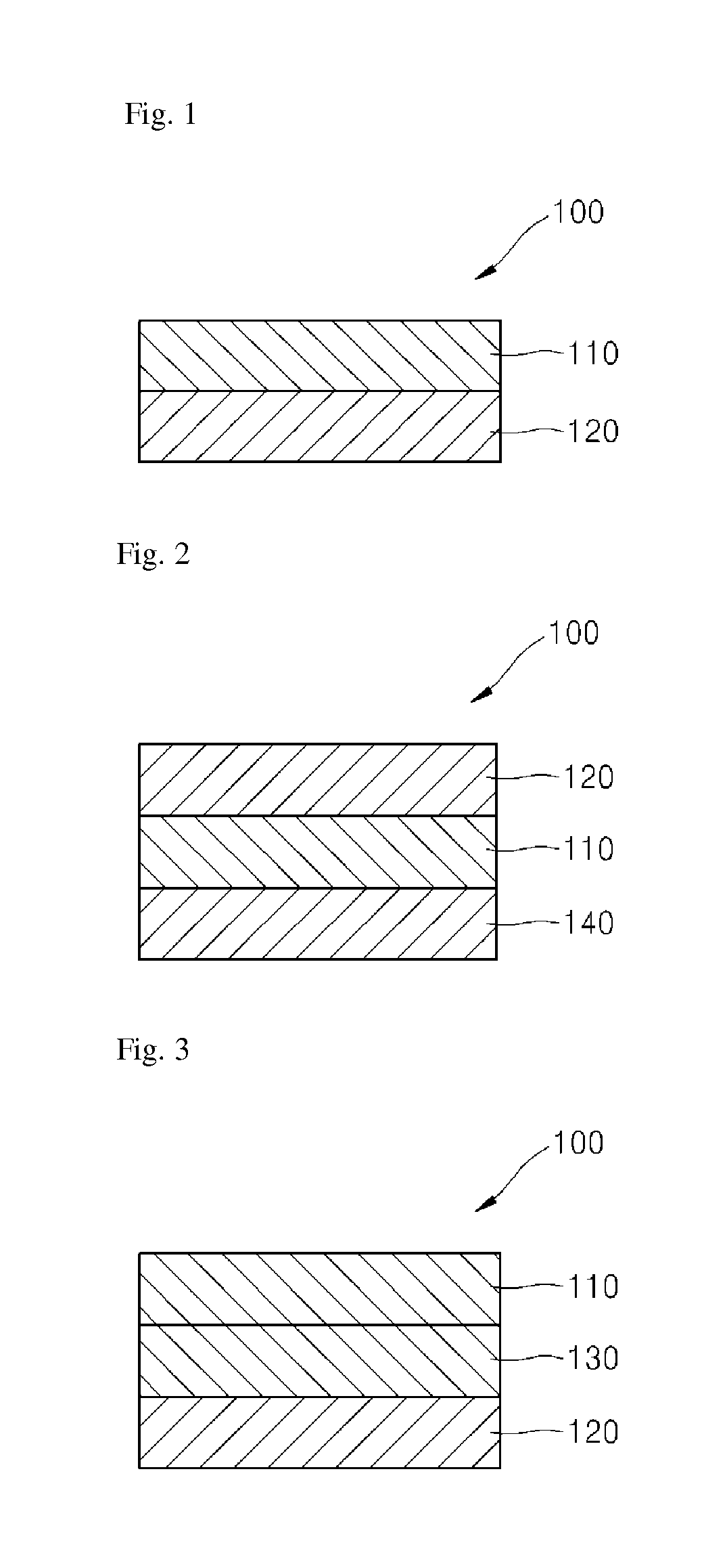
[0067]First, a core material formed of a composite material including a single layer of glass fiber wool and a single layer of glass fiber board as shown in FIG. 1 was manufactured to a size of 8 mm×190 mm×250 mm (thickness×width×length), and was applied to a vacuum insulation panel.

[0068]Next, an outer skin material having a laminate structure of a 12 μm thick polyvinylidene chloride (PVDC) / polyethylene terephthalate (PET) film, a 25 μm thick nylon film, a 7 μm thick aluminum foil, and a 50 μm thick linear low-density polyethylene (LLDPE) film was formed.

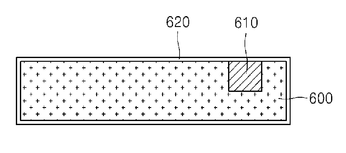
[0069]Then, two getters manufactured by placing 25 g of quicklime (CaO) having a purity of 95% in a pouch were inserted into the core material as shown in FIG. 9.

[0070]Next, the core material was sealed at a vacuum degree of 10 Pa after insertion into an encapsulant to manufacture the vacuum insulation panel according to the present invention.

example 2

[0071]The vacuum insulation panel was manufactured in the same manner as in Example 1, except that the core material was formed of a composite material in which a single layer of glass fiber board was stacked on two layers of glass fiber wool, and was manufactured to a size of 8 mm×190 mm×250 mm (thickness×width×length).


PUM

PropertyMeasurementUnit
Temperatureaaaaaaaaaa
Diameteraaaaaaaaaa
Diameteraaaaaaaaaa

Abstract

The present invention relates to a composite core material for a vacuum insulation panel which exhibits excellent initial insulation and long-term durability, a method of manufacturing the same, and a vacuum insulation panel using the same. The vacuum insulation panel includes a composite core material formed of glass fiber wool and a glass fiber board, and an outer skin material having a layered structure comprising a surface protective layer, a metal barrier layer, and a bonding layer from the outside to vacuum-package the core material.

Description

TECHNICAL FIELD[0001]The present invention relates to a vacuum insulation panel, and more particularly, to a vacuum insulation panel which includes a core material formed of at least two composite materials of glass fiber wool and a glass fiber board, thereby exhibiting excellent initial insulation and long-term durability.BACKGROUND ART[0002]A vacuum insulation panel is generally manufactured by receiving a continuous rigid cellular plastic foaming agent or an inorganic material as a core material in an encapsulant formed of a composite plastic laminate film exhibiting excellent gas barrier properties, reducing an inner pressure of the encapsulant, and heat-sealing stacked portions of gas barrier films along the circumference of the encapsulant.[0003]An inorganic compound having low thermal conductivity and generating a small amount of gas is suitable for the core material of the vacuum insulation panel. In particular, a vacuum insulation panel having a glass fiber stacked body as ...

Claims


Application Information

Patent Timeline
IPC IPC(8): B32B17/02B32B37/14D04H18/00
CPCB32B17/02D04H18/00B32B37/14B32B5/26B32B15/14B32B15/20B32B17/067B32B37/06B32B37/1027B32B37/1054B32B2250/02B32B2262/101B32B2305/20B32B2307/304B32B2309/02B32B2315/08B32B2607/00E04B1/803F16L59/065B32B15/08B32B27/08B32B27/12B32B27/304B32B27/36F25D2201/14D04H1/4218B32B15/04B32B27/18B32B3/08B32B2250/40B32B2260/021B32B2264/10B32B2264/102B32B2264/104B32B2307/30B32B2307/732Y02A30/242Y10T156/10Y10T428/231Y10T442/60Y10T442/623Y10T442/699Y02B80/10
Inventor HAN, JUNG - PILHWANG, SUNG - SEOCK
Owner LG HAUSYS LTD
Learn More