System and Method for Analyzing Spiral Resonators

a spiral resonator and spiral resonator technology, applied in the field of systems and methods for analyzing spiral resonators, can solve the problems of insufficient models for some applications, methods not necessarily producing the same, and inability to meet the requirements of the application,

a spiral resonator and spiral resonator technology, applied in the field of systems and methods for analyzing spiral resonators, can solve the problems of insufficient models for some applications, methods not necessarily producing the same, and inability to meet the requirements of the application,

US20130144588A1Inactive Publication Date: 2013-06-06MITSUBISHI ELECTRIC RES LAB INC

Image

  • System and Method for Analyzing Spiral Resonators
  • System and Method for Analyzing Spiral Resonators
  • System and Method for Analyzing Spiral Resonators

Examples


Embodiment Construction

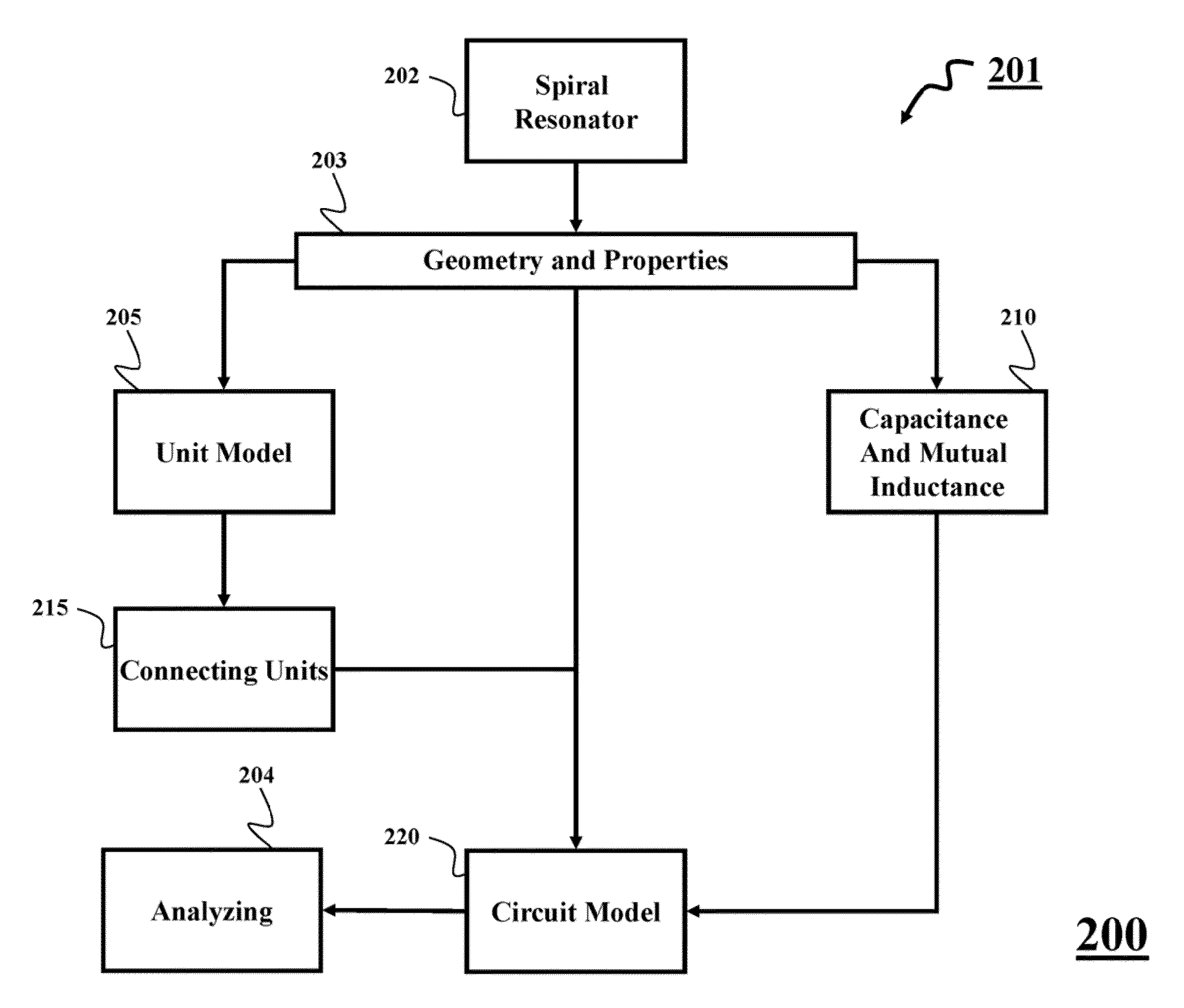
[0055]The embodiments of the invention provide a method for analyzing a spiral resonator.

[0056]Problem Formulation

[0057]A tank circuit model for analyzing a spiral resonator assumes a uniform current density throughout the length of the spiral(s). This assumption is incorrect, because the current density distribution resembles a standing wave in which the nodes of the standing wave are located at the open leads of the spiral resonator.

[0058]Another problem with the tank circuit model is that the model cannot be used to gain insight into the electromagnetic properties of each loop of the spiral resonator and the interaction between the loops. The tank circuit model is like a black box in which the geometric properties of the spiral resonator are the inputs and only the resonant frequency of the spiral resonator is the output. An additional flaw in the tank circuit model of a spiral resonator is that it implicitly implies that a spiral resonator only has a single resonant frequency. H...


PUM


Abstract

A spiral resonator is analyzed by modeling a set of loops of the spiral resonator with a model of a circuit including a set of units, wherein each unit includes a resistor and an inductor to model one loop of the spiral resonator. Values of the resistor and the inductor of each unit are based on properties of a corresponding loop. Electrical connection of the loops is modeled by electrically connecting the units in a corresponding order of the loops. A capacitive coupling in the spiral resonator is modeled by connecting adjacent units with at least one capacitor having a value based on the capacitive coupling between two corresponding adjacent loops. An inductive coupling in the spiral resonator is modeled based on inductive coupling between pairs of loops. The operation of the spiral resonator is simulated with the model of the circuit.

Description

RELATED APPLICATION[0001]This Application claims priority to U.S. Provisional Patent entitled, “Method for Modeling Spiral Resonators” Application No. 61 / 565,711, filed on Dec. 1, 2011. The provisional application is incorporated herein by reference.FIELD OF THE INVENTION[0002]This invention relates generally to systems and methods for analyzing spiral resonators, and more particularly to modeling and analyzing the spiral resonators based on circuit topologies.BACKGROUND OF THE INVENTIONSpiral Resonators[0003]Spiral resonators have a conductive material (wire(s)) with a spiral structure designed to resonate at one or multiple frequencies. The value of spiral resonators can be shown through their application to both a single layer spiral and a double layer spiral resonators. FIG. 1A shows an example of two common single layer spiral structures, i.e., a square spiral 105 and an Archimedes spiral 110. All the wires of the single layer spiral are arranged in the same plane.[0004]FIG. 1B...

Claims


Application Information

Patent Timeline
06 Jun 2013
Publication
US20130144588A1
IPC
G06F17/50
CPC
H03H2001/0092; H03H7/0115; G06F17/5063; G06F17/5036; G06F30/36; G06F30/367
Inventors
WANG, BINGNAN; ELLSTEIN, DAVID