Radiation generating apparatus
a technology of generating apparatus and generating liquid, which is applied in the direction of x-ray tubes, material analysis using wave/particle radiation, instruments, etc., can solve the problems of reducing the withstand voltage and deteriorating the insulating liquid, and achieves the reduction the withstand voltage. , the effect of suppressing the decrease of the withstand voltag
- Summary
- Abstract
- Description
- Claims
- Application Information
AI Technical Summary
Benefits of technology
Problems solved by technology
Method used
Image

Examples
example 1
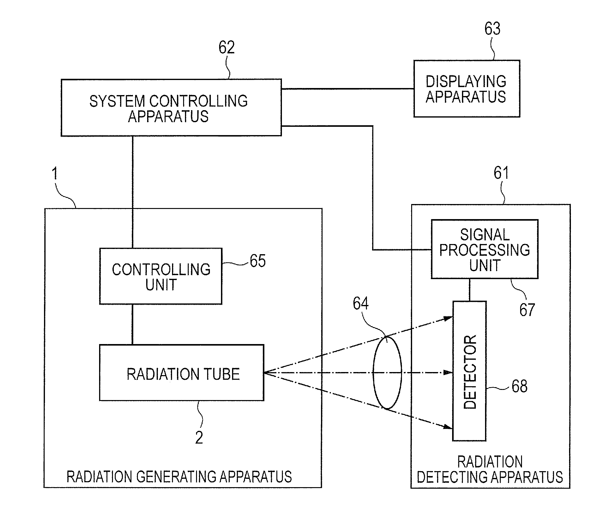
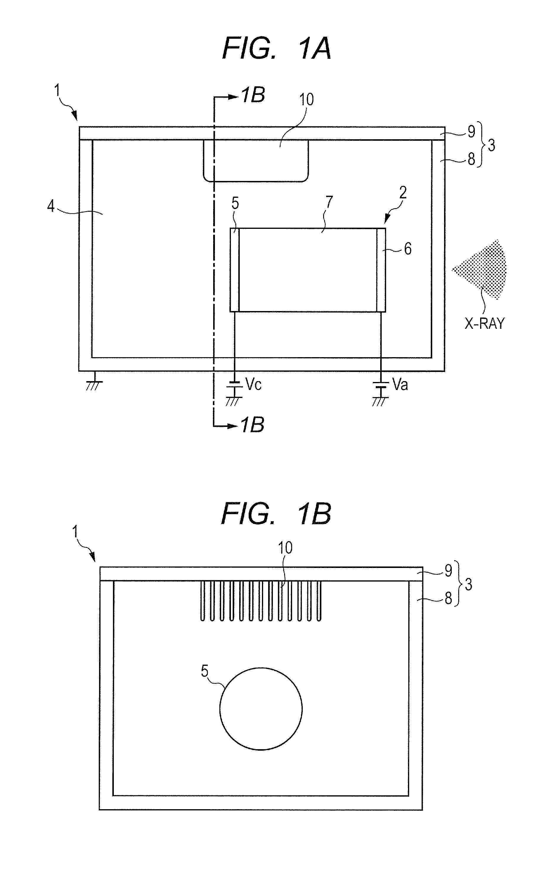
[0031]The constitution of a radiation generating apparatus in this example is the same as that exemplified in the above embodiment (FIGS. 1A and 1B).
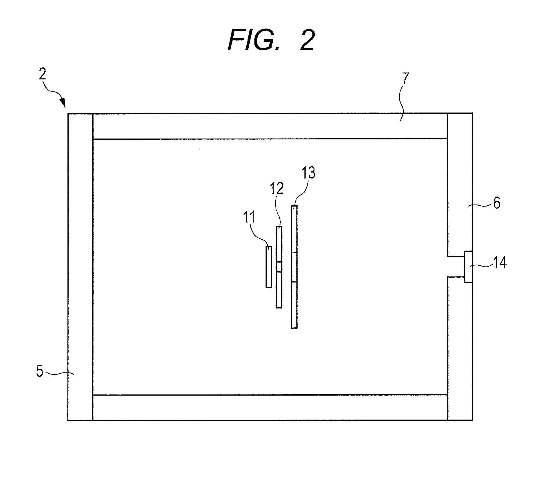
[0032]The radiation generating apparatus 1 is formed by enclosing the radiation tube 2 in an envelope and filling the insulating liquid 4 into the envelope. The radiation tube 2 is a transmission type radiation tube which is formed by holding the tubular side wall 7 between the cathode 5 and the anode 6 and sealing these members (FIG. 2). The electron gun structure (the electron source 11, the grid electrode 12, and the focusing electrode 13) based on the anode potential is connected with the cathode 5, and the target 14 is provided at the anode 6. The kovar is used for the cathode 5 and the anode 6, and the alumina is used for the tubular side wall 7, and they were bonded with each other by a brazing method. The shape of the cathode 5 and the anode 6 was formed as a circular form and the shape of the tubular side wall 7 was formed as a...
example 2
[0037]The constitution of a radiation generating apparatus 1 in this example is different from the constitution of the Example 1. The projecting length of the fin from the cover unit 9 is decreased according as the fin 10 approaches closer to the cathode 5 as illustrated in FIGS. 3A and 3B. That is, the fin 10 was provided so as to increase a distance between the fin 10 and a barrel portion of the radiation tube 2 to become a long distance according as the potential difference between the fin 10 and a barrel portion of the radiation tube 2 becomes a large difference. In addition, a fin 15 which becomes a symmetric relation with the fin 10 for the radiation tube 2 was provided on a surface opposite to the cover unit 9 of the envelope 3. Excepting the above different points, the constitution of this example is the same as that of the Example 1.
[0038]In the Example 1, since the potential difference between the fin 10 and a barrel portion of the radiation tube 2 becomes a large differen...
example 3
[0041]The constitution of a radiation generating apparatus in this example is different from the constitution of the Example 2. As illustrated in FIG. 4, the anode 6 was defined as the ground potential, and the fins 10 and 15 were arranged only on the periphery of the anode 6. Excepting this different point, the constitution is the same as that of the Example 2. The potential definition as in this example is generally called as a grounded-anode. In case of the grounded-anode, the intensity of the potential difference between the cathode 5 and the envelope 3 becomes double the intensity, and a distance between the radiation tube 2 and the envelope 3 is also required to become double the distance. Therefore, when the fins 10 and 15 are provided, the envelope 3, of which the size is more increased, is required. However, when the fins 10 and 15 are arranged only on the periphery of the anode (preferably, a portion between the anode 6 and the envelope 3) as in this example, the size incr...
PUM
 Abstract
Description
Claims
Application Information
 - R&D
- Intellectual Property
- Life Sciences
- Materials
- Tech Scout
- Unparalleled Data Quality
- Higher Quality Content
- 60% Fewer Hallucinations
Browse by: Latest US Patents, China's latest patents, Technical Efficacy Thesaurus, Application Domain, Technology Topic, Popular Technical Reports.
© 2025 PatSnap. All rights reserved.Legal|Privacy policy|Modern Slavery Act Transparency Statement|Sitemap|About US| Contact US: help@patsnap.com