
Jet engine

Inactive Publication Date: 2013-06-20
MART NEZ CASAN JOSE RAMON
View PDF10 Cites 2 Cited by
  • Summary
  • Abstract
  • Description
  • Claims
  • Application Information

AI Technical Summary

Benefits of technology

This patent is about a new engine that is designed to be fast, efficient, and use less energy than other engines. It has a compressor that has four blades that adjust themselves using springs inside them. The engine also has two retainers that work in the axial direction to secure the blades in place. This design allows for better adjustment and ensures a tight seal in the engine. Overall, this new engine has improved performance and efficiency compared to other engines.

Problems solved by technology

Relatively cold air can be used to cool the combustion chamber and the turbine blades and prevent them from melting.Post combustor: mainly used in military airplanes, it produces an additional thrust, burning fuel in the nozzle area, generally inefficiently, to increase the inlet temperature of the nozzle.Nozzle or outlet: hot gases leave the engine towards the atmosphere through a nozzle, whose goal is to produce an increase in the speed of these gases.
The main drawbacks of scramjets are those related to cooling due to heating at high speeds.

Method used


Image

  • Jet engine
  • Jet engine
  • Jet engine

Examples


Embodiment Construction

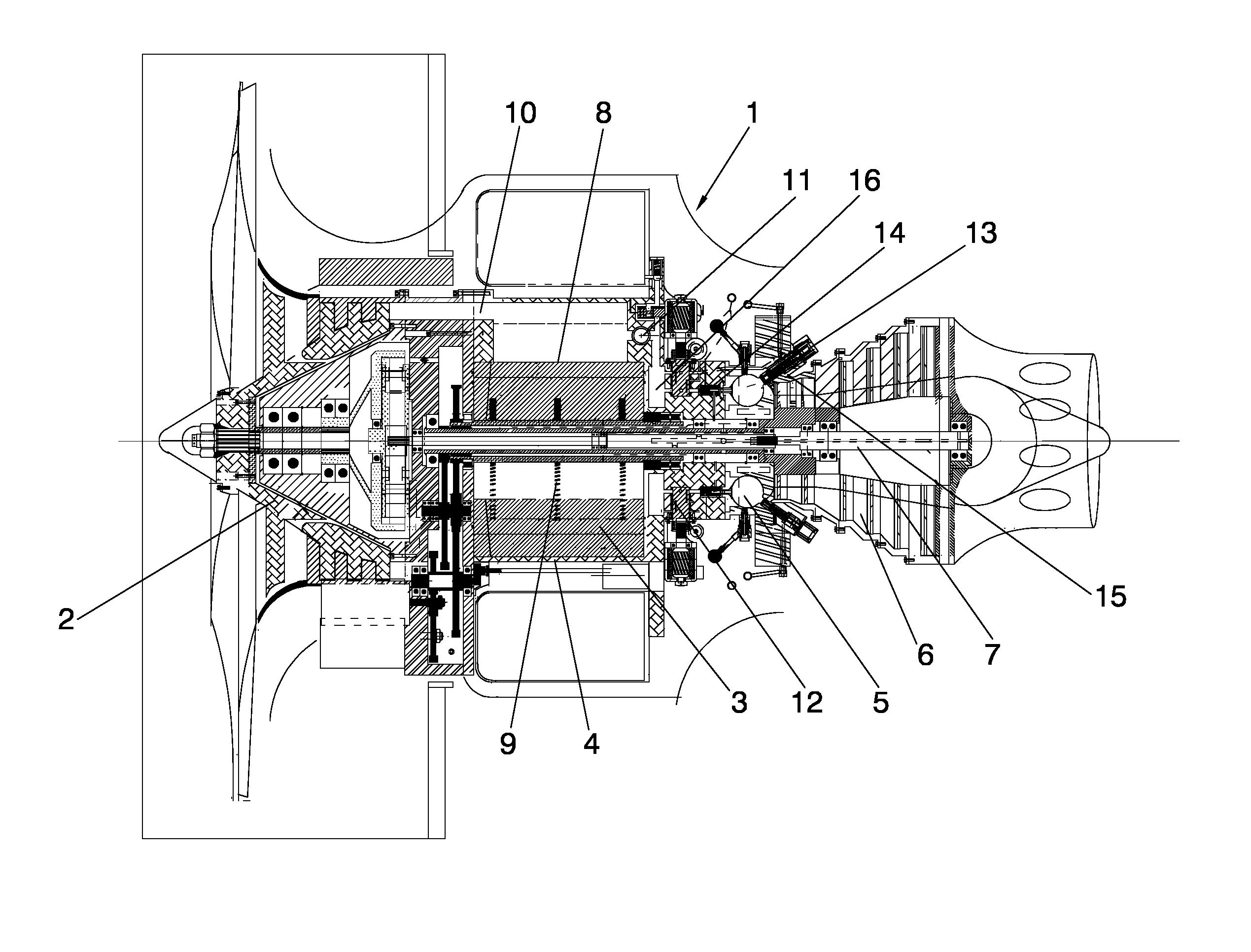
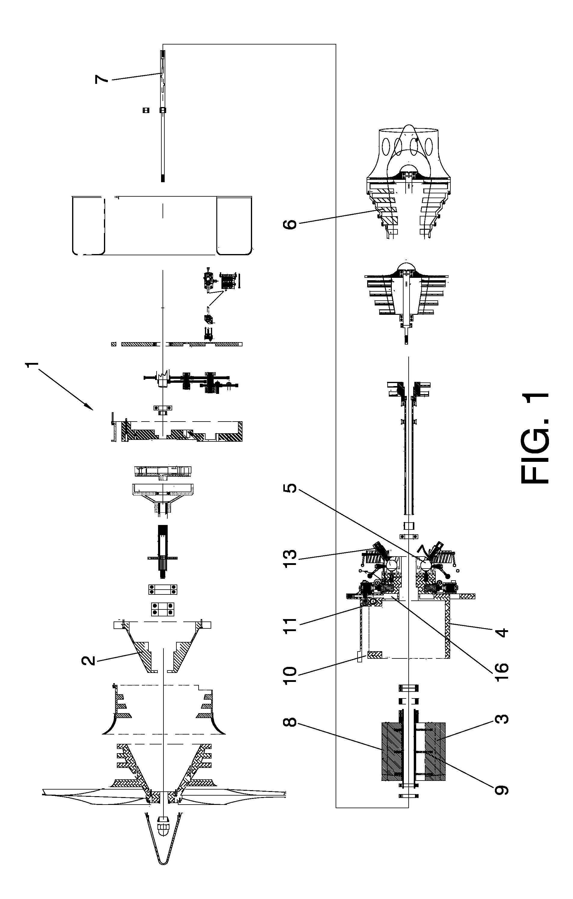
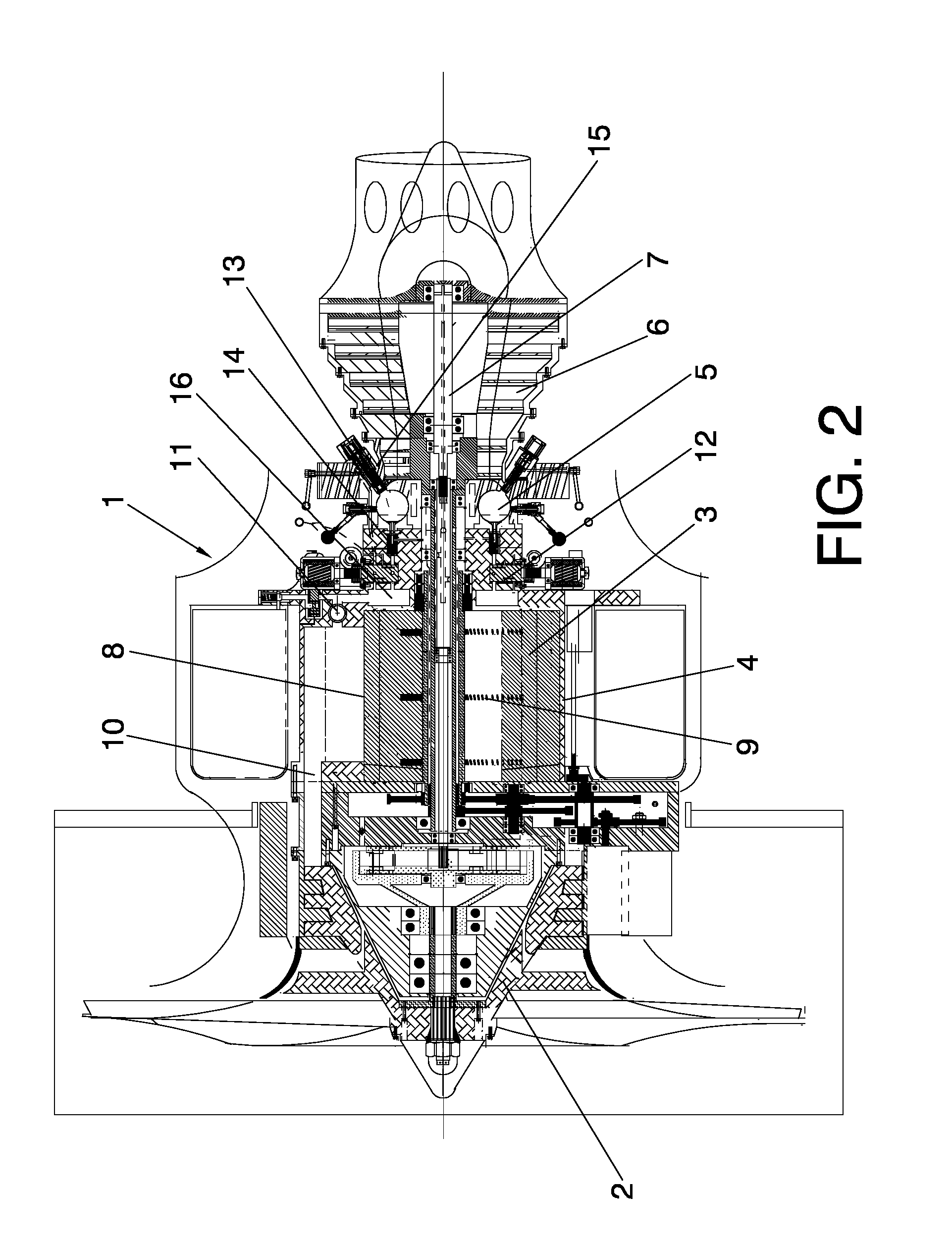
[0017]The object of the invention is a high performance, energetically efficient engine, which features a compressor block defined by a high speed, eccentric rotor turbo compressor with a rotor that, in a preferred embodiment of the object of invention, comprises four self-adjusting, cross-sectioned blades—self-adjusting, since they are equipped with adjusting mechanisms defined by springs inserted in the interior thereof—on the stator with automatic recovery. This system facilitates closure in the radial direction while closure in the axial direction is carried out by two retainer rings situated on the two inner faces of the stator.

[0018]The aforementioned stator has an air inlet channel situated in the cool part of the stator and is responsible for supplying the turbo compressor. This duct connects to an inlet channel situated in the rotor chamber and is offset 45° with respect to the air exhaust channel, already compressed. The shutoff between the two channels is ensured by means...


PUM


Abstract

A reaction engine is disclosed mainly intended for aviation, but which as described herein can be adapted for an industrial engine, which makes use of spherical chambers and a pressure system in the blades of the rotor-stator unit which permits a perfect adjustment between said blades and the inner face of the stator, preventing pressure losses. While edges likewise articulated in the same way as the blades, execute a labyrinth seal.

Description

OBJECT OF THE INVENTION[0001]The present invention pertains to the field of reaction engines.[0002]The object of the invention consists of an improved reaction engine which, thanks to its special characteristics, allows for better performance.BACKGROUND OF THE INVENTION[0003]A turbojet engine is a type of internal combustion engine frequently used to propel an aircraft. The air is dragged to a rotary compressor through the air intake and is compressed, during several successive stages, at high pressure before entering the combustion chamber. The fuel is mixed with the compressed air and ignited. This combustion process considerably increases the temperature of the gas. The result of the combustion leaves to expand through the turbine, where the energy is extracted to move the compressor. Although this expansion process reduces both the temperature and the gas pressure, they are both generally kept higher than the averages thereof. The flue gas leaving the turbine expands to the atmo...

Claims


Application Information

Patent Timeline
IPC IPC(8): F02K3/06
CPCF01C11/006F02C3/055F02K3/06F01C21/0845F04C23/006F04C2/344F04C25/00F04C28/24F04C29/0021F04C29/0085F04C23/02
Inventor MART NEZ CASAN, JOSE RAMON
Owner MART NEZ CASAN JOSE RAMON
Features
  • Generate Ideas
  • Intellectual Property
  • Life Sciences
  • Materials
  • Tech Scout
  • Unparalleled Data Quality
  • Higher Quality Content
  • 60% Fewer Hallucinations
Learn More