
Lithographic imaging and printing without defects of electrostatic origin

a technology of electrostatic origin and lithographic imaging, which is applied in the direction of rotary lithographic machines, lithography, transportation and packaging, etc., can solve the problems of electrostatic discharge (“esd”) events, accumulated charge trapped in these regions, and plate structure types that tend to undergo triboelectric charging, etc., to achieve fast and efficient cleaning and ease removal

Active Publication Date: 2013-06-27
MARK ANDY
View PDF1 Cites 0 Cited by
  • Summary
  • Abstract
  • Description
  • Claims
  • Application Information

AI Technical Summary

Benefits of technology

The patent describes a method for printing using a special printing member. The printing member has three layers: an oleophobic layer, a polymeric layer with carbon particles, and an oleophilic layer. The printing member is exposed to imaging radiation to remove some of the polymer layer and make it water compatible, and then it is exposed to an aqueous liquid to remove the imaging layers and create the desired pattern. The printing member is then used in a printing press to transfer ink to the desired area without buildup of triboelectric charge. The technical effects of this method are faster and more efficient cleaning with a better pattern quality and reduced defects in the printed copy.

Problems solved by technology

This type of plate structure has a tendency to undergo triboelectric charging during printing due to repetitive cycles of contact with and separation from the press form rollers (which, like the topmost polymer plate layer, are made of insulating material).
As a result, the accumulated charge is trapped in these regions.
The latter can lead to electrostatic discharge (“ESD”) events, when sudden and uncontrolled transfer of static charge occurs.
The electrostatic energy is converted into heat that can cause severe damage to the fine features of an imaged plate, leading to unacceptable print-work.
These solutions are cumbersome and expensive, and frequently unrealistic in a commercial printing environment.

Method used


Image

  • Lithographic imaging and printing without defects of electrostatic origin
  • Lithographic imaging and printing without defects of electrostatic origin
  • Lithographic imaging and printing without defects of electrostatic origin

Examples


examples 1 and 2

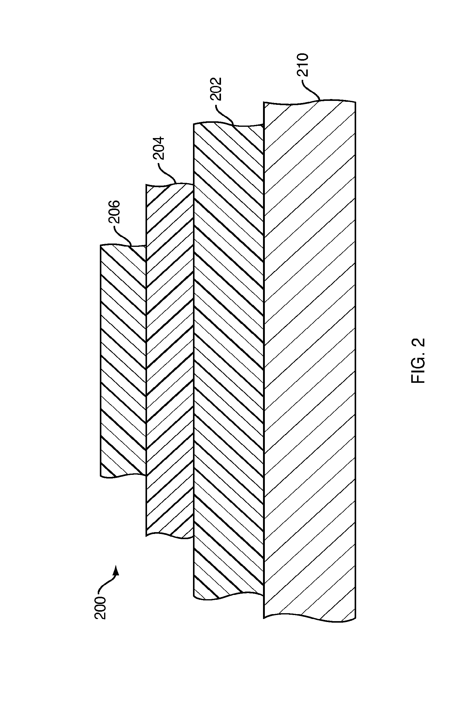
[0070]Waterless printing plates in accordance with the invention generally include a carbon-polymer composite imaging layer 204 and an oleophobic top layer 206 disposed on a polyester substrate 202. A preferred substrate is a 175 μm white polyester film sold by DuPont Teijin Films (Hopewell, Va.) labeled MELINEX 331.

[0071]Suitable formulations for the carbon-polymer imaging layer are described below.

PartsComponentExample 1Example 2HRJ 123621.461.82Micropigmo AMBK-25.83—Renol Black RH HW30—9.56Cymel 3850.440.55Cycat 40400.440.55BYK 3070.090.09Dowanol PM91.75 87.44 

[0072]HRJ-12362 is a phenol formaldehyde thermosetting resin supplied as a 72 wt % solid in a 60% n-butanol solution by the SI Group, Inc. (Schenedtady, N.Y.). MICROPIGMO AMBK-2 is a 20% solids proprietary carbon dispersion supplied by Orient Corporation of America (Kenilworth, N.J.). RENOL BLACK R-HW 30 is a carbon black preparation available from Clariant International Ltd. (Switzerland) in a granular form with a low-visc...

examples 3-5

[0080]Plates similar to those of Example 2 were prepared using carbon imaging formulations with different polymer co-binder resins. Formulation examples are given below for carbon layers made with the RENOL BLACK RH-HW30 carbon dispersion, but the MICROPIGMO AMBK-2 dispersion could also have been used.

PartsComponentExample 3Example 4Example 5Vinnol E-15 / 48A1.82——Novolak P2—1.82—Acryloid B-44——1.82Renol Black RH HW309.569.569.56Cymel 3850.550.550.55Cycat 40400.550.550.55BYK 3070.090.090.09Dowanol PM87.66 87.66 87.66 

[0081]VINNOL E-15 / 48A is a vinyl chloride coating resin with hydroxyl functional groups available from Wacker Chemie AG (Germany). NOVOLAK P2 is an o-cresol and p-cresol phenolic resin supplied by Diversitec Corporation (Fort Collins, Colo.). ACRYLOID B-44 is a solid thermoplastic acrylic resin available from Rhom and Haas (Philadelphia, Pa.).

[0082]These carbon formulations were applied with a wire-round rod and dried and cured at 178° C. for about one minute to provide a...

example 6

[0084]In this example, the carbon and silicone layers as described in Example 1 were applied as described above onto a 200 μm (0.008 inch) anodized aluminum alloy (Alcoa, Pittsburgh, Pa.). The alloy was electrochemically etched and anodized to provide an anodic layer with Ra values in the order of 0.300 μm.

[0085]The plate was imaged, cleaned and ran on a Presstek 34 DI digital offset printing press as described in Examples 1 and 2. The cleaning process allows for complete removal of the silicone layer and partial removal of the carbon-loaded imaging layer in the exposed areas of the plate. Any residual carbon left on the exposed areas enhances the ink receptivity of the image areas of the plate. This printing member was run for more than 1,000 impressions without showing any ESD defects.


PUM

PropertyMeasurementUnit
temperatureaaaaaaaaaa
thicknessaaaaaaaaaa
thicknessesaaaaaaaaaa

Abstract

Embodiments of the present invention involve three-layer printing members having a central layer that is non-conductive yet abalatable at commercially realistic fluence levels. In various embodiments, the central layer is polymeric with a dispersion of nonconductive carbon black particles therein at a loading level sufficient to provide at least partial layer ablatability and water compatibility of the resulting ablation debris.

Description

BACKGROUND OF THE INVENTION[0001]In offset lithography, a printable image is present on a printing member as a pattern of ink-accepting (oleophilic) and ink-rejecting (oleophobic) surface areas. Once applied to these areas, ink can be efficiently transferred to a recording medium in the imagewise pattern with substantial fidelity. In a wet lithographic system, the non-image areas are hydrophilic, and the necessary ink-repellency is provided by an initial application of a dampening fluid to the plate prior to inking. The dampening fluid prevents ink from adhering to the non-image areas, but does not affect the oleophilic character of the image areas. Ink applied uniformly to the wetted printing member is transferred to the recording medium only in the imagewise pattern. Typically, the printing member first makes contact with a compliant intermediate surface called a blanket cylinder which, in turn, applies the image to the paper or other recording medium. In typical sheet-fed press s...

Claims


Application Information

Patent Timeline
Patent Type & Authority Applications(United States)
IPC IPC(8): B41C1/10
CPCB41C1/1016B41C1/1033B41C2201/02B41N1/003B41C2210/02B41C2210/262B41C2210/14B41C2210/20B41C2210/22B41C2210/24B41C2210/06Y10T428/31678Y10T428/31663Y10T428/31786B41N1/14
Inventor RONDON, SONIARAY, KEVIN
Owner MARK ANDY
Features
  • Generate Ideas
  • Intellectual Property
  • Life Sciences
  • Materials
  • Tech Scout
  • Unparalleled Data Quality
  • Higher Quality Content
  • 60% Fewer Hallucinations
Learn More