Transmission interference microscope

a technology of interference microscope and transmission image, which is applied in the direction of microscopes, instruments, electric discharge tubes, etc., can solve the problems of increasing the resolution of the cone, difficult to obtain the complete interference fringe, and the method is unsuitable for application to a technique requiring a pure transmission image such as tomography, and achieves high magnification and high accuracy of interference images

Inactive Publication Date: 2013-06-27
HITACHI HIGH-TECH CORP
View PDF8 Cites 7 Cited by
  • Summary
  • Abstract
  • Description
  • Claims
  • Application Information

AI Technical Summary

Benefits of technology

[0024]According to the present invention, the electron beam 6 passing through the sample and the electron beam 7 passing through the vacuum are adjustable so as to be left a space at a given distance therebetween, and the sample can be irradiated by nearly collimated beams. The present invention can solve the problem in the method of irradiating charged particles onto the sample in the interference apparatus, and can provide a degree of freedom to the observation region while obtaining the information on transmission by the collimated beams. The present invention allows obtaining the electron beam 7 which passes through the vacuum without being affected by the electrostatic charge of the sample under optimized irradiation conditions, and allows obtaining highly accurate interference images at high magnification.

Problems solved by technology

In addition to this problem of limiting the observation region, there has been another problem, that is, the problem that an electrical charge on the sample resulting from the converged electron beam being irradiated thereon, affects the electron beam 7 passing through the vacuum, and thereby making complete interference fringes difficult to be obtained.
On the other hand, in this method, the sample is irradiated by a converged electron beam and the information on the electromagnetic field is obtained for the entire region irradiated with a cone-shaped electron probe at a given observation point during scanning, consequently, when the sample has a thickness, a resolution becomes greater for the diameter of the cone-shaped electron probe, which makes the method unsuitable for application to a technique requiring a pure transmission image such as a tomography method.
However, such desired could not have been reached with a conventional holography method or a conventional scanning interference electron microscope.

Method used


Image

  • Transmission interference microscope
  • Transmission interference microscope
  • Transmission interference microscope

Examples


example 1

[0031]FIG. 4 is a schematic view of an electron beam holography apparatus according to Example 1 of the present invention.

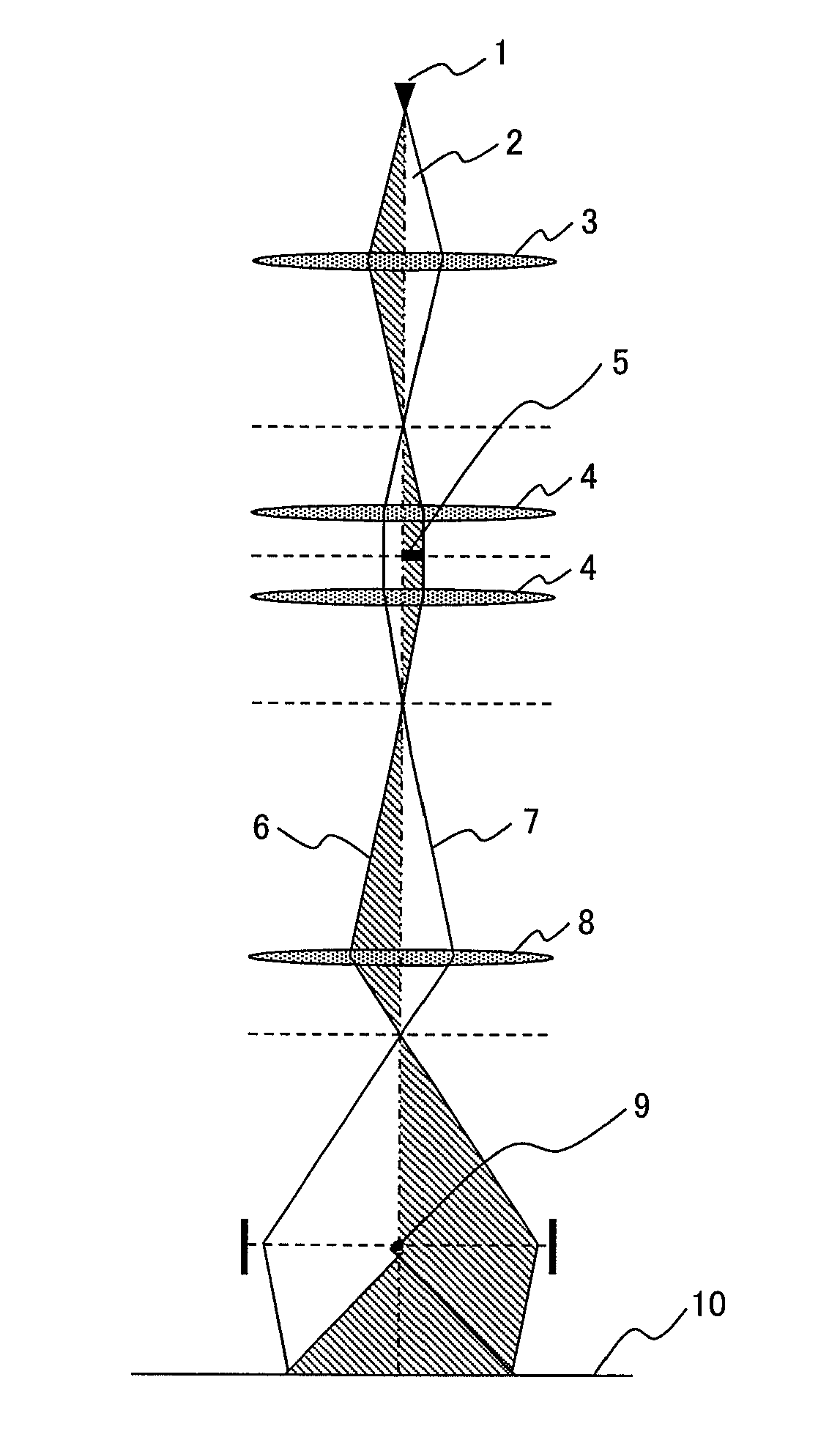
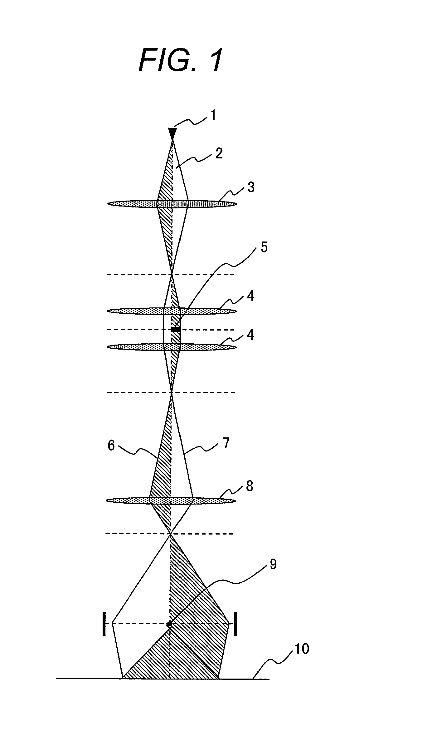
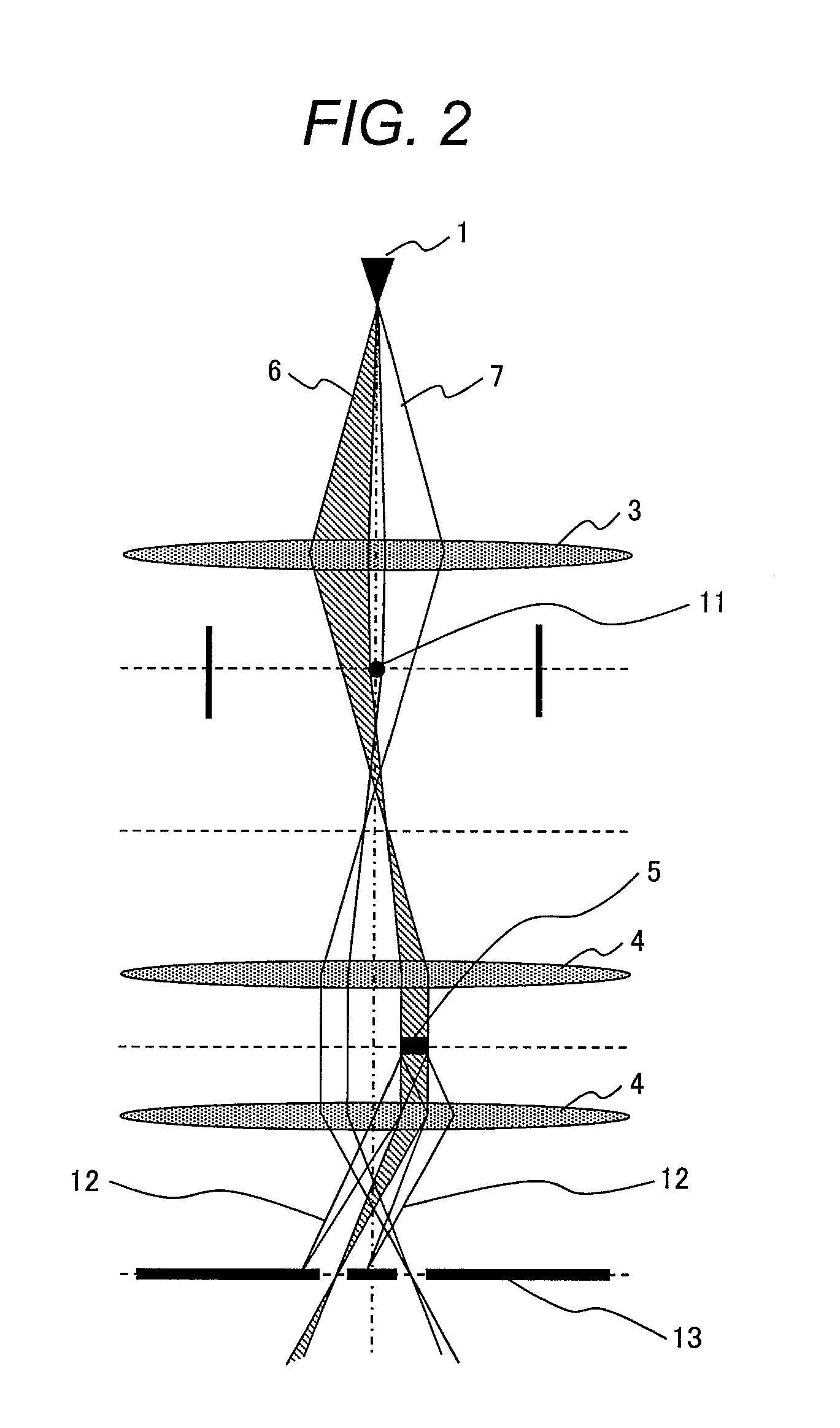
[0032]The electron beam holography apparatus according to the present invention has, in the same manner as a general-purpose interference microscope, a mirror body 14, a control PC 15, and a monitor 16, and the mirror body 14 is evacuated by an evacuating device not illustrated in the figure. The mirror body 14 comprises an electron source 1, a first extraction electrode 17, a second extraction electrode 18, an acceleration electrode 19, a converging lens 3, a biprism 11, objective lenses 4, a sample micro-moving mechanism 20, an objective aperture 13 having two apertures, an objective aperture micro-moving mechanism 21, a magnifying lens 8, a biprism 9, and an electron beam detector 22. The lenses, the biprisms, the sample micro-moving mechanism, the objective aperture micro-moving mechanism, and the electron beam detector are controlled by the control PC 15 thr...


PUM


Abstract

Disclosed is a transmission interference microscope that provides a degree of freedom to a region being observed while obtaining pure transmission information, and obtains highly-accurate interference images at high magnification under optimized radiation conditions. An electron beam emitted from an electron source 1 is split by a biprism 11 positioned under a converging lens 3, and enters objective lenses 4 as an electron beam 6 passing through a sample and an electron beam 7 passing through a vacuum. The electron beams are bent at the front magnetic fields of the objective lenses 4, and are emitted as a collimated beam in a state in which the sample location and vacuum are each appropriately are left a space.

Description

TECHNICAL FIELD [0001]The present invention relates to a charged particle beam interference apparatus and relates to a transmission interference microscope using an electron beam.BACKGROUND ART [0002]An electron beam biprism interference apparatus measures a phase shift of an electron beam to quantitatively measure an electromagnetic field of a substance or an electromagnetic field in a vacuum.[0003]FIG. 1 shows an interference optical system used in a conventional electron beam holography method.[0004]In FIG. 1, an electron beam 2 emitted from an electron source 1 runs as shown in the figure while being converged by a converging lens 3 and then passing through objective lenses 4.[0005]A sample 5 is placed on one side of an optical axis between the objective lenses 4; an electron beam 6 which has transmitted (passed) through the sample and an electron beam 7 which has passed through a vacuum without passing through the sample are magnified with a magnifying lens 8, bent inward by a ...

Claims


Application Information

Patent Timeline
Patent Type & Authority Applications(United States)
IPC IPC(8): G02B21/00
CPCH01J37/26H01J2237/2614H01J2237/248H01J37/04H01J2237/045G02B21/00
Inventor NAGAOKI, ISAOTANIGAKI, TOSHIAKI
Owner HITACHI HIGH-TECH CORP
Why Eureka
Try Eureka