
Enhanced vegetative roof system

a vegetative roof and enhanced technology, applied in the field of enhanced vegetative roof systems, can solve the problems of lowering the temperature in city environments, large air gaps between modules, and affecting energy efficiency and acoustic insulation

Active Publication Date: 2013-07-04
WESTON SOLUTIONS
View PDF9 Cites 17 Cited by
  • Summary
  • Abstract
  • Description
  • Claims
  • Application Information

AI Technical Summary

Benefits of technology

The vegetative roof system described in this patent allows for the growth of plants on roofs using modules that communicate with each other. The modules have rooting channels that allow plant roots to extend between them, sharing moisture and nutrients. The modules can be locked together using a connector to enhance stability. The system also includes liquid retention reservoirs and drainage apertures to manage excess fluids. The technical effects of this system include promoting biodiversity, facilitating plant growth on roofs, and improving the stability of the roof.

Problems solved by technology

Due to the ability of plants to transpire and also provide shade, significant use of vegetative roofs throughout large cities can cause a cooling effect, lowering the temperature in city environments.
Such sidewalls result in large air gaps between the modules, impacting energy efficiency and acoustic insulation.
The exposed areas of adjacent modules can also form exposed black plastic seams that may heat up rapidly in sunlight, heating the airspace and causing uneven drying-out of the contents around the perimeters of the modules, with adverse effects on some types of plants.
Conventional sidewalls thus do not allow adjacent modules to “communicate” (i.e., to exchange airflow, nutrients, moisture, etc. between and among each other).
They also do not allow the roots of plants to extend beyond the boundaries of the individual modules, confining and restricting growth media to the detriment of plant health.

Method used


Image

  • Enhanced vegetative roof system
  • Enhanced vegetative roof system
  • Enhanced vegetative roof system

Examples


Embodiment Construction

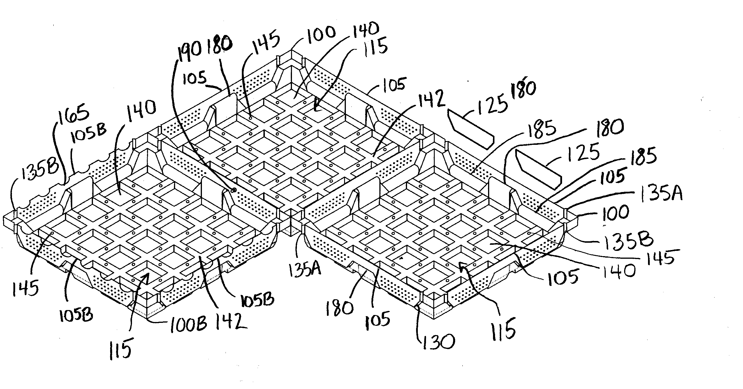
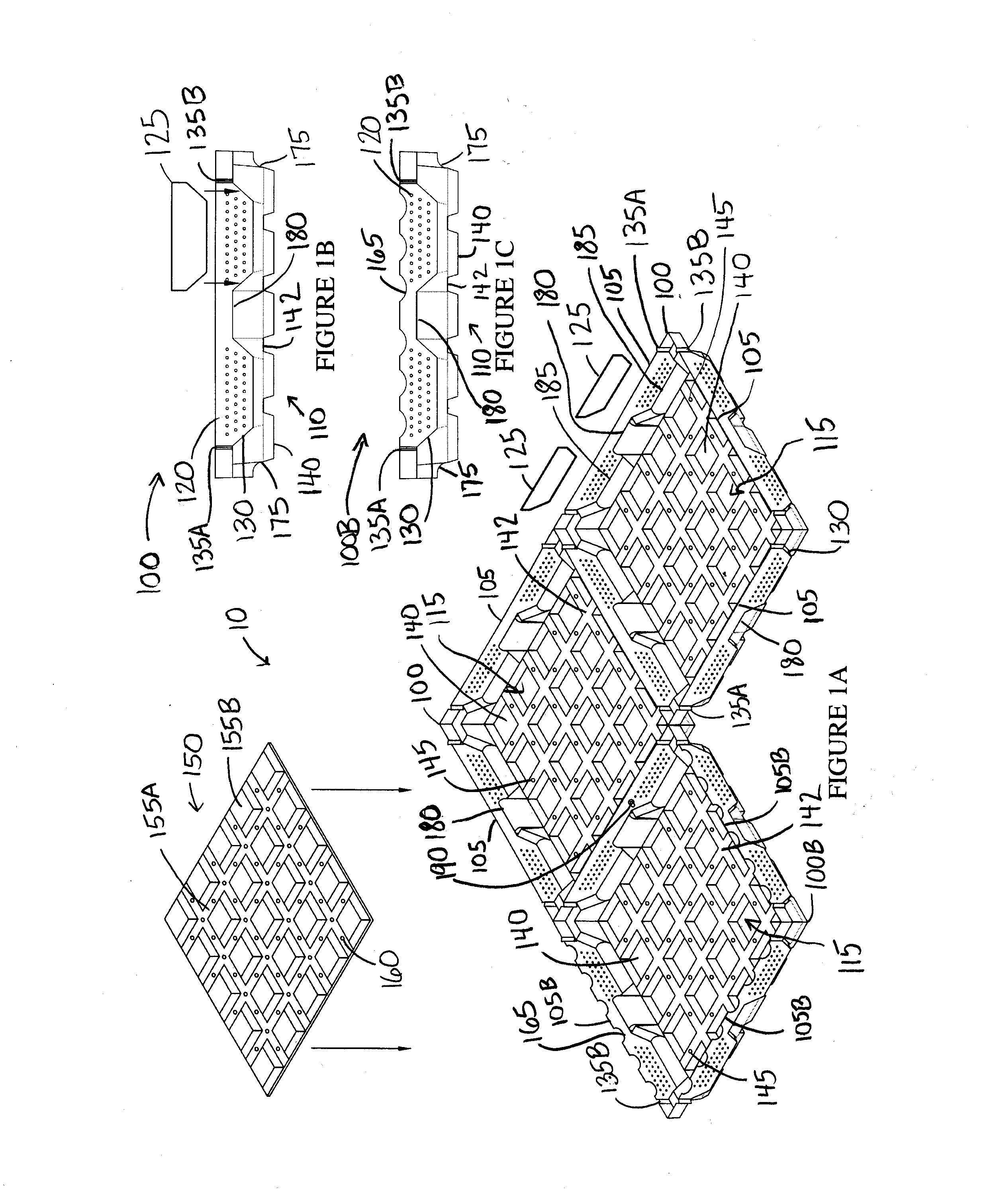
[0014]Returning to FIGS. 1A and 3 the exemplary vegetative roof system 10 is made up of one or more individual, easily-moveable modules 100 or panels. Four sidewalls 105 rise upwardly to various heights to define the interior volume 115 that can contain components of the vegetative roof system 10 (such as engineered growth media 305, filter fabrics, plants, etc.). Individual modules 100 can be placed side-by-side on a roof to fully cover a designated area, resulting in a visually uniform stand of vegetation. Modules 100 are removable as needed to, for example, perform underlying roof repairs. The vegetative system provides for enhanced modularity and improves on hybrid or monolithic systems. Features such as full height sidewalls 105 with a perimeter edge flush with the level of growth media 305 (see FIG. 3) facilitates the separation and removal of a module 100 from adjoining modules 100. This enhances access in the vegetative roof system 10, enabling removal without significant di...


PUM


Abstract

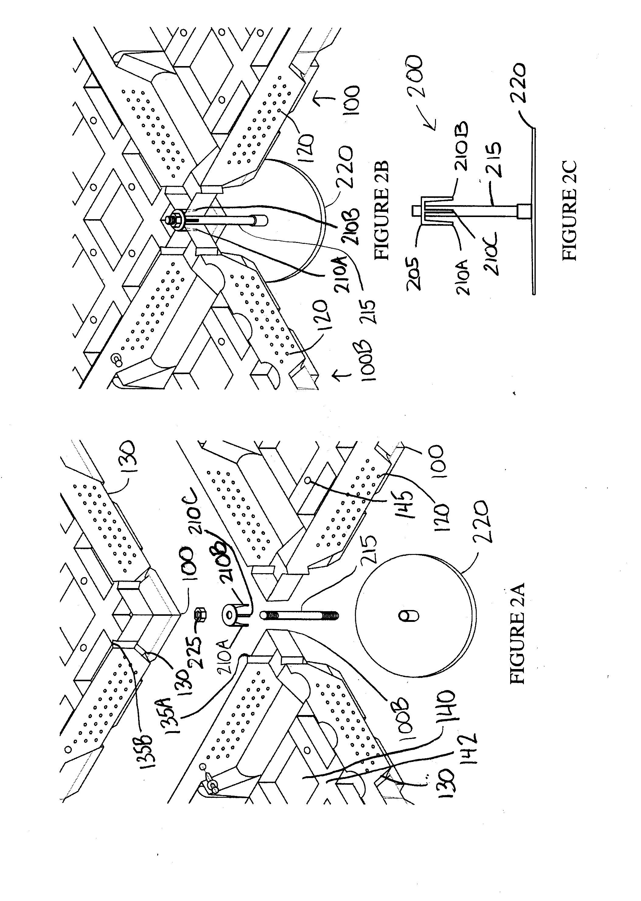
A vegetative roof system includes modules for holding growth media in which plants can grow. The modules can communicate with each other, sharing moisture / nutrients, increasing airflow to enhance plant respiration, allowing soil-borne animals / insects to travel between modules, etc. A rooting channel and / or a scalloped sidewall allow the roots of plants in the module to extend to adjacent modules. Alignment notches in sidewalls facilitate alignment of rooting channels between adjacent modules. Vertical zones help facilitate placement of abutting modules flush with each other. The rooting channels may be formed at the vertical zones to enhance continuity between and among modules. Sheet inserts can control rooting between modules and restrict undesired spillage through rooting channels (temporarily if biodegradable). Module inserts help control the quantity and depth of growth media, affecting module weight and rooting levels. An elevated connector can secure two or more modules together using downwardly-radiating prongs.

Description

[0001]This application claims priority under 35 USC §119(e) to U.S. Provisional Patent Application 61 / 445,647 filed Feb. 23, 2011, the entirety of which is incorporated by reference herein.FIELD OF THE INVENTION[0002]This document concerns an invention relating generally to an enhanced vegetative roof system including a module capable of communicating with adjacent modules.BACKGROUND OF THE INVENTION[0003]A “vegetative roof” (or “green roof”) refers to the environmentally-friendly addition of growth media and vegetation (i.e., plants) to the roof of a building. Vegetative roofs have environmental and economic benefits over traditional black or white-reflective membrane roofs, enhancing stormwater management, reducing energy costs, and extending roof lives. Heat is not retained in vegetative roofs the way it is in black roofs; thus, the city may be able to cool faster. Vegetative roofs can thus reduce the urban heat island effect common to most large cities. Due to the ability of pla...

Claims


Application Information

Patent Timeline
Patent Type & Authority Applications(United States)
IPC IPC(8): A01G1/00
CPCE04D11/002Y02B80/32A01G1/007Y02A30/254A01G9/033
Inventor FISCHER, KURT T.HANZELY, THOMAS M.BAUMANN, KATHY M.MCFARLAND, TIMOTHYSELLERS, DARRAN
Owner WESTON SOLUTIONS
Learn More