Brushless motor speed control system

a technology of motor speed control and brushless motor, which is applied in the direction of torque ripple control, single motor speed/torque control, dynamo-electric machines, etc. it can solve the problems of inability to create images, inability to seamlessly integrate these two complimentary commutation modes using presently available methods and technologies, and insufficient resolution of hall sensors to drive the motor consistently. , to achieve the effect of smooth low speed control, greater peripheral functionality, and smooth operation

Active Publication Date: 2013-07-04
BOSCH SECURITY SYST INC
View PDF14 Cites 29 Cited by
  • Summary
  • Abstract
  • Description
  • Claims
  • Application Information

AI Technical Summary

Benefits of technology

[0007]With the introduction of advanced programmable controllers employing greater peripheral functionality and including integrated PWM drivers, much smoother operation of dual mode brushless motor controllers is now possible. New software capabilities with greater sampling rates not only permit smoother operation in both commutation modes, but also smoother transition between modes. In this design, no expensive digital encoders are required at low speeds, yet fine motor resolution is possible, enabling clear images even at rotation rates of one per month or less. At the same time, a high speed mode, with nominal speeds of up to 100 degrees per second, is available without the speed limitations and overheating of the stepper motor mode. The resulting control system requires fewer complex and expensive parts, a simpler implementation, and provides an exceptionally wide speed range suitable for long range surveillance imaging of consistent clarity.
[0012]The system achieves smooth low speed control without the need for digital encoders, by the programmable controller synchronously driving multiple PWMs, sine wave modulated, in the low speed mode.
[0021]g) an auxiliary control card can allow for three independent integrated circuit bus protocol ports so that pan, tilt and zoom positions can be fed to it from each position, thereby enabling external dedicated secure control pathways for panning, tilting and zooming;
[0034]r) the low speed mode operates when the brushless motor has an rpm number less than a presselected number in the range of 200-300 rpm, the high speed mode operates when the brushless mote has an rpm number greater than a preselected number in the range of 200-300 rpm; and the transition phase occurs at a transition speed in the range of 200-300 rpm, in order to effect smooth operation of the brushless motor speeds above and below the transition speed;
[0041]The brushless motor control system thus provides a wide range of smooth and precisely controlled speeds for pan-tilt-zoom surveillance cameras, using a seamless combination of high and low speed commutation modes for a brushless motor. The system preloads PID and lookup table registers used by a programmable controller for a smooth transition from high speed mode to low speed mode, and from low speed mode to high speed mode, phase locking a sine position during transitions, in order to give a surveillance camera an ability to quickly move from one target to another at up to 100 degrees per second yet track objects that are moving very slowly.

Problems solved by technology

The issue with brushless motors employing hall sensors for high speed block commutation timing is that the hall sensors do not provide enough resolution to drive the motor consistently at low speeds.
At high speeds, this method operates smoothly, but at low speeds, they cannot create an image without noticeable blurring caused by the lowered positional discrimination in this mode.
Smooth low speed operation of brushless motors is possible by operating as a stepper motor with sinusoidal synchronous commutation, but the seamless integration of these two complimentary commutation modes is not available using presently available methods and technologies.

Method used


Image

  • Brushless motor speed control system
  • Brushless motor speed control system
  • Brushless motor speed control system

Examples


Embodiment Construction

[0051]All elements will first be introduced by reference to figures, then the functionality and interactions of each element with each other element will be described, and finally the preferred embodiment of the novel device will be described in detail.

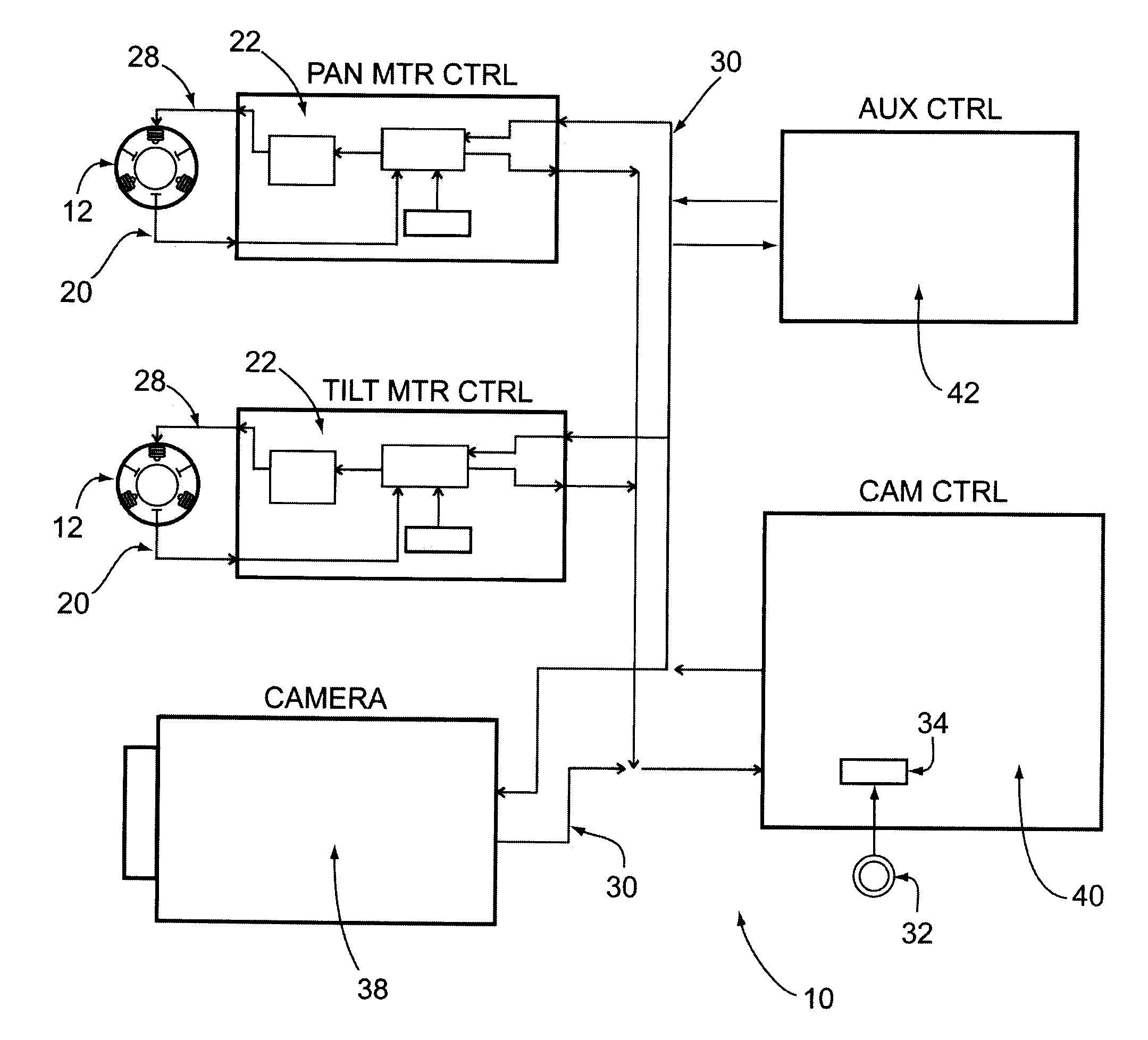
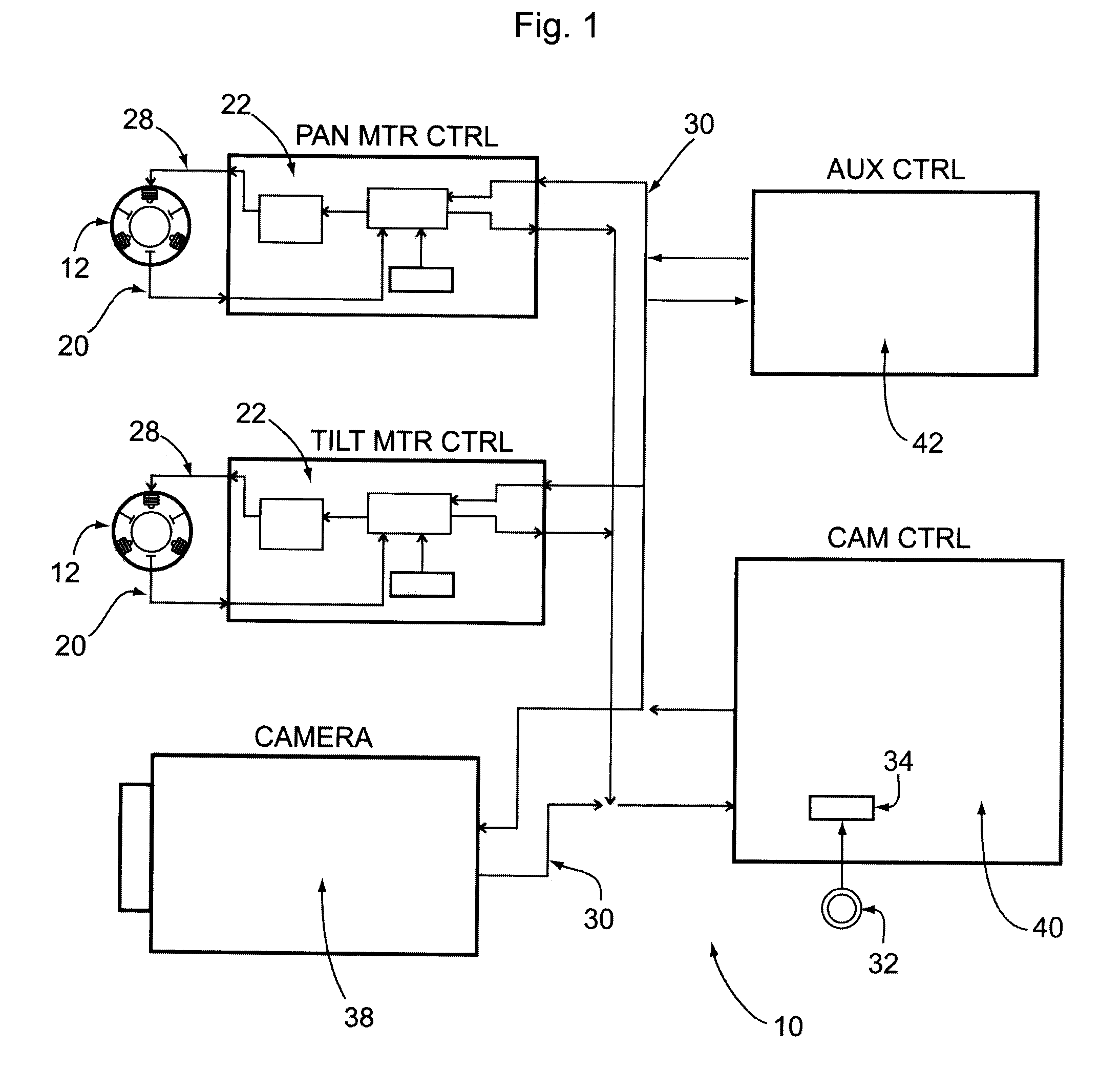
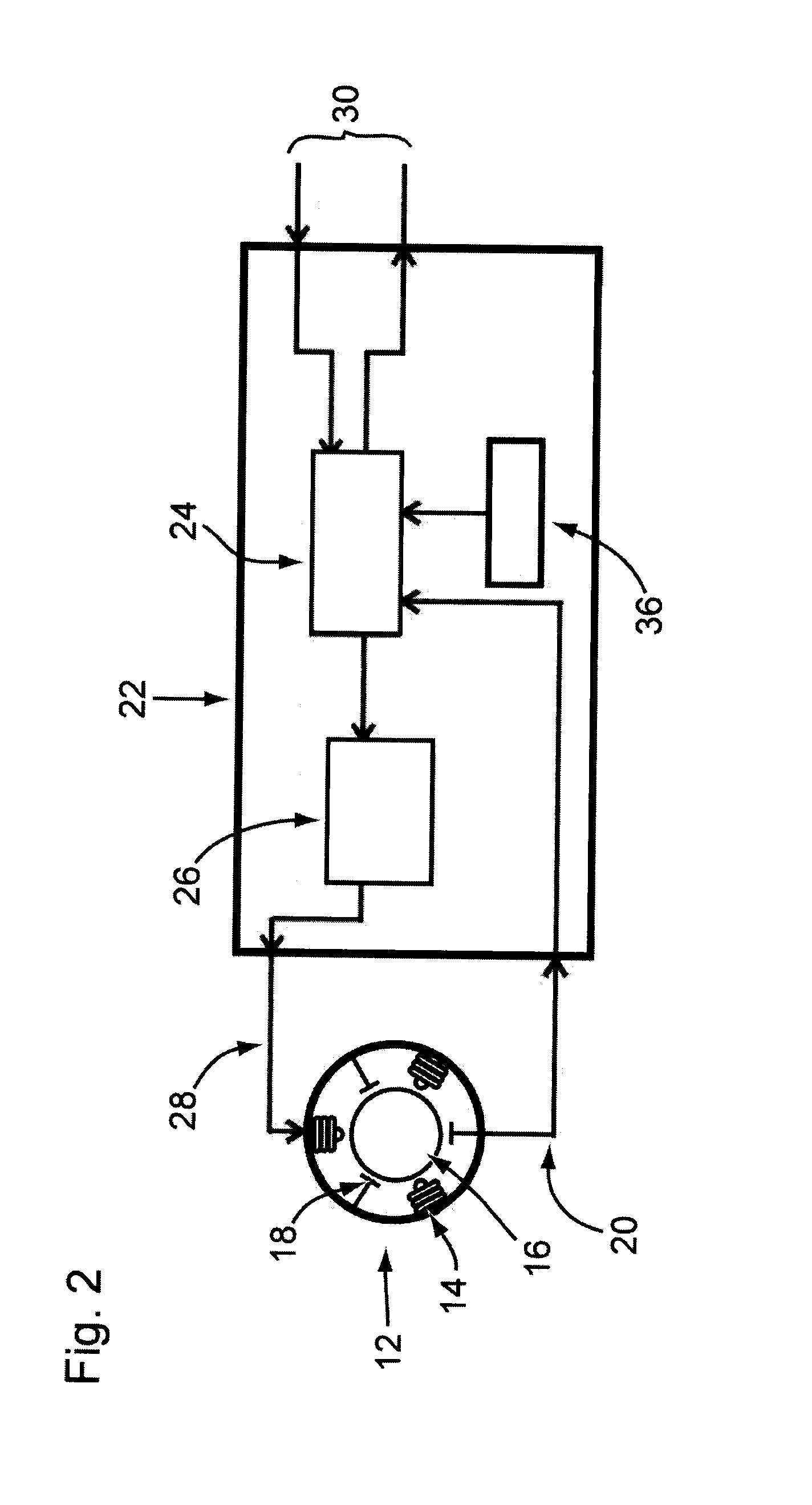
[0052]FIG. 1 diagrams the entire Brushless Motor Speed Control System 10 wherein each motor driver card 22 receives Hall sensor outputs 20 from the motor 12, and depending on the operating mode and the required speed, provides the appropriate PWM output 28 to drive the motor 12. A camera control card 40 can issue VISCA (Video System Control Architecture) formatted commands on a TTL serial bus 30 to either Pan or Tilt motor driver cards 22, or to the camera 38. Motor driver cards 22 can command each motor 12 to go to a specific position, report the current position by means of a digital resolver 32, drive at a specific speed and direction and stop (see FIG. 8). There will also be commands to read back data such as current speed and PWM...


PUM


Abstract

This system provides a wide range of smooth and precisely controlled low and high speeds for pan-tilt-zoom surveillance cameras, in which a brushless motor is controlled by a Microcontroller in a low speed mode by sinusoidal synchronous commutation, in a high speed mode by block commutation, and in in a transition phase from the low speed mode to the high speed mode by modulating integrated pulse-width modulation (PWM) square waves with sine waves. PID and lookup table registers are used by a microcontroller for a smooth transition from high speed mode to low speed mode, and from low speed mode to high speed mode, phase locking a sine position during transitions, in order to give a surveillance camera an ability to quickly move from one target to another at up to 100 degrees per second yet track objects that are moving very slowly.

Description

FIELD OF INVENTION[0001]This invention relates to a novel device in the general field of motor control systems, and more specifically to one which permits a wider range of speeds for brushless motors as used in pan-tilt-zoom surveillance cameras.BACKGROUND OF THE INVENTION[0002]Surveillance cameras are commonly directed to move at high speed so they can identify and track a potential intruder as early as possible. However, it has been found that very slow moving threats are not always detected by some surveillance cameras because they are not capable of operating at very slow tracking speeds, and because slow speed operation presents unique technological challenges to produce recognizable images. Motorized panning and tilting of surveillance cameras at a wide range of speeds require motors that can operate smoothly at both high and low speeds. While high speed operation can effectively use brushless motors in block commutation modes, low speed operation using the same mode can degra...

Claims


Application Information

Patent Timeline
Patent Type & Authority Applications(United States)
IPC IPC(8): H02P7/00
CPCH02P6/08H02P6/181H02P7/00H02P2209/07H02P25/026H02P25/03H02P6/10
Inventor MARKHAM, RICHARD
Owner BOSCH SECURITY SYST INC
Why Eureka
Try Eureka