Roll detection and six degrees of freedom sensor assembly

a technology of rolling detection and sensor assembly, applied in the field of electromagnetic positioning sensor, can solve the problems of increasing cost, reducing the service life of the coil, so as to achieve the effect of increasing the cos

Active Publication Date: 2013-07-04
ST JUDE MEDICAL INT HLDG SARL
View PDF6 Cites 103 Cited by
  • Summary
  • Abstract
  • Description
  • Claims
  • Application Information

AI Technical Summary

Benefits of technology

[0008]Various embodiments herein provide a positioning sensor assembly for a medical device that can detect roll without increasing cost by using additional separate sensors, without obstructing the central lumen of the medical device, and without unduly enlarging the medical device. Accordingly, in at least one embodiment, such a sensor assembly may include a coil

Problems solved by technology

However, the design of a coil assembly that can provide such functionality provides challenges, particularly with respect to space constraints.
The sensor can detect three degrees of position (X, Y, and Z), as well as pitch and

Method used


Image

  • Roll detection and six degrees of freedom sensor assembly
  • Roll detection and six degrees of freedom sensor assembly
  • Roll detection and six degrees of freedom sensor assembly

Examples


first embodiment

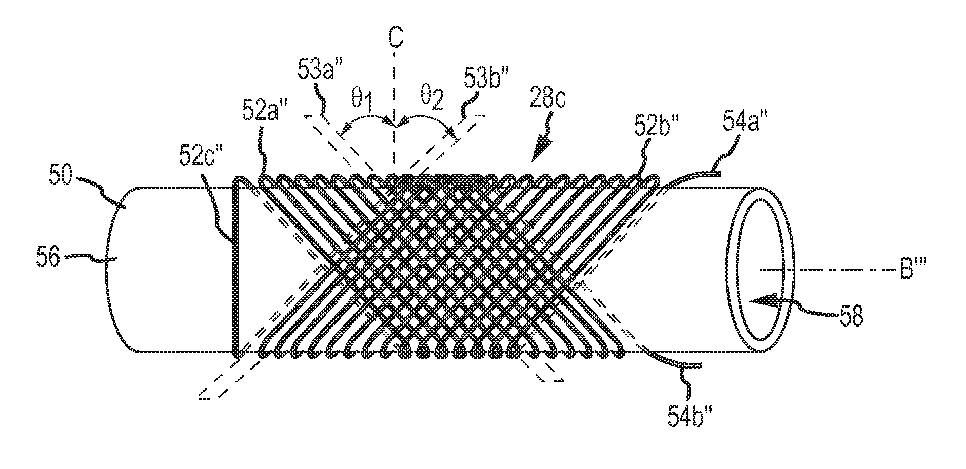
[0047]FIG. 6A is an isometric view of an electromagnetic position sensor, designated sensor 28a, that is configured to have a current induced therein for use in detecting roll or rotation about a longitudinal axis defined by at least a portion of sensor 28a. Sensor 28a may include a hollow sensor core 50 and a sensor coil 52 situated substantially in a plane 53 and with two free ends 54a, 54b. Core 50 may be an elongated hollow tube extending along longitudinal axis B′ having an outer surface 56 and a central through-bore 58 extending between opposing axial ends. Bore 58 may be configured to allow sensor 28a to be threaded on or applied to medical devices, among other things. Radially-outermost surface 56 may act as a winding surface for coil 52. In turn, coil 52 may be wound on outer surface 56 about axis B′ with free coil ends 54a, 54b left exposed for use as leads in connecting coil 52 to MPS 22. It should be noted that axis B′ is shown superimposed outside the surface of core 50...

fourth embodiment

[0058]FIG. 8 is an isometric view of a roll-sensing position sensor, designated sensor 70. Sensor 70 comprises a flexible printed circuit board (PCB), as described in co-pending U.S. patent application Ser. No. 13 / 232,536, entitled “Method for Producing a Miniature Electromagnetic Coil Using Flexible Printed Circuitry”, which is hereby incorporated by reference in its entirety as though fully set forth herein. A brief description of the flexible PCB of sensor 70 will be set forth below. The above-referenced application may be consulted for greater detail about the design and manufacture of flexible PCBs.

[0059]Sensor 70 includes an electrically insulative, relatively flexible substrate 72 and an electrically conductive trace 74 disposed (i.e., “printed”) on a first surface of substrate 72. Trace 74 is arranged in a pattern configured to create a sensing coil 80 when the substrate 72 is folded or formed into the final shape shown. The shape formed with substrate 72 extends along an ax...


PUM


Abstract

A roll-detecting sensor assembly includes a coil extending along and disposed about an axis. The coil comprises one or more portions, with each portion defining a winding angle. At least one of the portions defines a winding angle that is substantially nonzero relative to a line perpendicular to the axis, whereby the projected area of the coil in an applied magnetic field changes as the coil rotates about the axis. As a result, the coil is configured to produce a signal responsive to the magnetic field indicative of the roll of the sensor about the axis. In an embodiment, at least one of the portions defines a winding angle that is at least 2 degrees. In an embodiment, at least one of the portions defines a winding angle that is about 45 degrees.

Description

BACKGROUND OF THE INVENTION[0001]a. Field of the Invention[0002]The present disclosure relates generally to an electromagnetic positioning sensor for a medical device, and more specifically to an electromagnetic positioning sensor that can sense roll.[0003]b. Background Art[0004]Medical devices such as guidewires, catheters, introducers and the like with electromagnetic coil position sensors for device navigation are used in various medical procedures in the body. For example, it is known to equip a catheter with multiple coils sufficient to allow a positioning sensor to detect six (6) degrees-of-freedom (DOF), namely, a three-dimensional (3D) position (X, Y, Z) and a 3D orientation (e.g., roll, pitch, yaw) thereof. However, the design of a coil assembly that can provide such functionality provides challenges, particularly with respect to space constraints.[0005]One known electromagnetic position sensor includes a coil wound symmetrically on a tubular core. Such a sensor may be seen...

Claims


Application Information

Patent Timeline
IPC IPC(8): G01R33/04G01R33/02
CPCA61B5/062A61B19/5244A61B2019/5251A61B8/0841A61B6/12A61B6/487A61B2019/5278A61B2090/3782A61B34/20A61B2034/2051A61B90/37
Inventor EICHLER, UZIIZMIRLI, ALONSETER, DAN
Owner ST JUDE MEDICAL INT HLDG SARL
Why Eureka
Try Eureka