Ultrasonic Reactor Water Level Measuring Device and Evaluation Method

a technology of ultrasonic reactors and measuring devices, which is applied in the direction of instruments, nuclear elements, greenhouse gas reduction, etc., can solve the problems of reducing the accuracy of measurement, and achieve the effects of improving the accuracy of water level measurement, reducing the sn ratio, and small attenuation of ultrasonic waves

Active Publication Date: 2013-07-11
HITACHI-GE NUCLEAR ENERGY LTD
View PDF1 Cites 8 Cited by
  • Summary
  • Abstract
  • Description
  • Claims
  • Application Information

AI Technical Summary

Benefits of technology

The patent text describes a device for measuring the level of water in a reactor vessel. The device uses ultrasonic waves to determine the water level, but there are limitations to the accuracy of the measurement due to changes in the energy of the waves and the distance from the water surface. The invention solves this problem by using multiple measurement tubes at different stages, which reduces attenuation and the need for an envelope signal. The device also includes a separation valve to prevent water vapor leaks and can confirm the soundness of the device using waveforms of the ultrasonic waves. This improves the accuracy of the water level measurement over a wide range of levels.

Problems solved by technology

As a result, the accuracy of the measurement may be reduced.

Method used


Image

  • Ultrasonic Reactor Water Level Measuring Device and Evaluation Method
  • Ultrasonic Reactor Water Level Measuring Device and Evaluation Method
  • Ultrasonic Reactor Water Level Measuring Device and Evaluation Method

Examples


first embodiment

[0017]A first embodiment of the ultrasonic reactor water level measuring device according to the invention is described with reference to FIGS. 1 to 5.

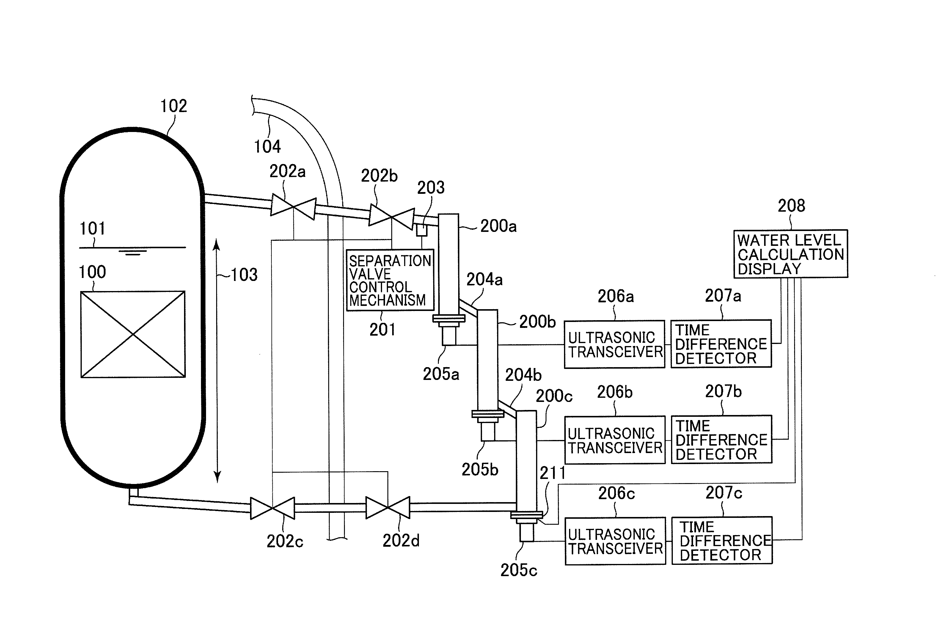
[0018]FIG. 1 is a schematic diagram illustrating a case in which the ultrasonic reactor water level measuring device according to the invention is applied to a boiling water reactor.

[0019]A reactor core 100 made of a nuclear fuel is stored in a reactor pressure vessel 102, while a water level 101 is a vertical position of the surface of a coolant within the reactor pressure vessel 102. A water level measurement range 103 is from a lower portion of the reactor pressure vessel 102 to a level located near a separator (not illustrated). Since water level measurement tubes 200a, 200b and 200c are arranged outside the reactor pressure vessel 102, a person can approach the water level measurement tubes 200a, 200b and 200c even when the reactor operates. A tube is connected between an upper portion of the reactor pressure vessel 102 and an up...

second embodiment

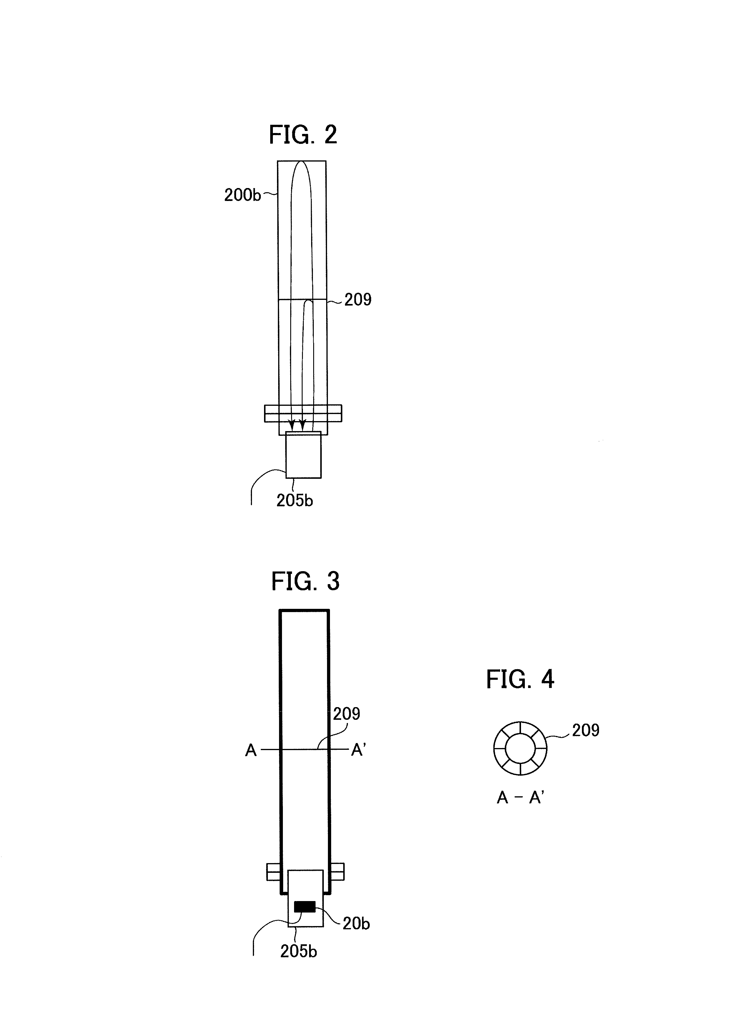
[0041]When the ultrasonic waves are transmitted into the measurement tubes, a part of the ultrasonic waves may propagate onto a tube wall and be scattered and mixed with a wave reflected from the liquid surface and may reduce a temporal resolution of the measurement of the period of time for the wave reflected from the liquid surface to reach the ultrasonic probe.

[0042]To avoid this, ultrasonic probes 210 that each have a lens with a concave surface may be used as illustrated in FIG. 6. The concave surfaces can suppress the spread of ultrasonic beams transmitted by the ultrasonic probes 210 and reduce noise. The concave surfaces are in contact with the water.

[0043]The following effects can be obtained in the second embodiment.

[0044]Since noise can be reduced by using the ultrasonic lenses in the ultrasonic reactor water level measuring device, the accuracy of the measurement of the water level can be improved. Thus, an effect of improving the performance of the ultrasonic reactor wa...


PUM


Abstract

An ultrasonic reactor water level measuring device and an evaluation method are provided and prevent a reduction in the measurement accuracy of a water level that is in a wide measurement range. The ultrasonic reactor water level measuring device includes an upper tube extending from a gas phase portion in a reactor, a lower tube extending from a liquid phase portion in the reactor, measurement tubes connected to each other and arranged at multiple stages between the upper tube and the lower tube, and units for generating and receiving ultrasonic waves, the units being arranged at bottom portions of the measurement tubes. The ultrasonic reactor water level measuring device measures levels of water within the measurement tubes and calculates a water level within the reactor from the sum of the measured water levels, the sum excluding an overlapped part of the measurement tubes.

Description

BACKGROUND OF THE INVENTION[0001]1. Field of the Invention[0002]The present invention relates to an ultrasonic reactor water level measuring device that uses ultrasonic waves to measure a water level of a reactor such as a boiling water reactor. The invention also relates to a method for evaluating the soundness of the ultrasonic reactor water level measuring device.[0003]2. Description of the Related Art[0004]An ultrasonic water level meter that includes an ultrasonic probe, a time meter and a water level calculator is known in the art. The ultrasonic probe transmits an ultrasonic signal into a fluid. The time meter measures a propagation time between the transmission of the ultrasonic signal to the surface of the fluid within a waveguide, and return of the ultrasonic signal from the surface of the fluid. The water level calculator calculates a water level on the basis of the propagation time and executes temperature compensation. Since the propagation time is a round-trip propagat...

Claims


Application Information

Patent Timeline
Patent Type & Authority Applications(United States)
IPC IPC(8): G01F23/296G01F25/00
CPCG01F23/2962G21C17/035G01F25/0076G01F25/0061Y02E30/30G01F25/24G01F25/20
Inventor YAMADA, IZUMIFUSHIMI, ATSUSHIBABA, ATSUSHIMURATA, AKIRAASANO, TAMOTSUHAMA, RYUTAKOYAMA, MIKIOKATSUYAMA, HIROAKIMUSHA, YOSHINORI
Owner HITACHI-GE NUCLEAR ENERGY LTD
Why Eureka
Try Eureka