This helps you quickly interpret patents by identifying the three key elements:
Problems solved by technology
Method used
Benefits of technology
Benefits of technology
The patent text describes a way to make a chemical system that captures CO2 more energy efficient. This is done by reducing the energy needed to regenerate the absorbent and by reusing the heat from cooling the exhaust gas. The patent introduces specific techniques for achieving this, such as using a heat exchanger to absorb the heat from the exhaust gas and use it to cool the absorbent. Overall, this results in a more energy efficient system for capturing CO2.
Problems solved by technology
However, with regard to the CO2 capture system by chemical absorption described in each of the cited patent literatures, nothing is proposed about specific techniques to reduce energy and reduce and reuse waste heat.
Method used
Image
Click on the blue label to locate the original text in one second.
Reading with bidirectional positioning of images and text.
Examples
embodiment 1
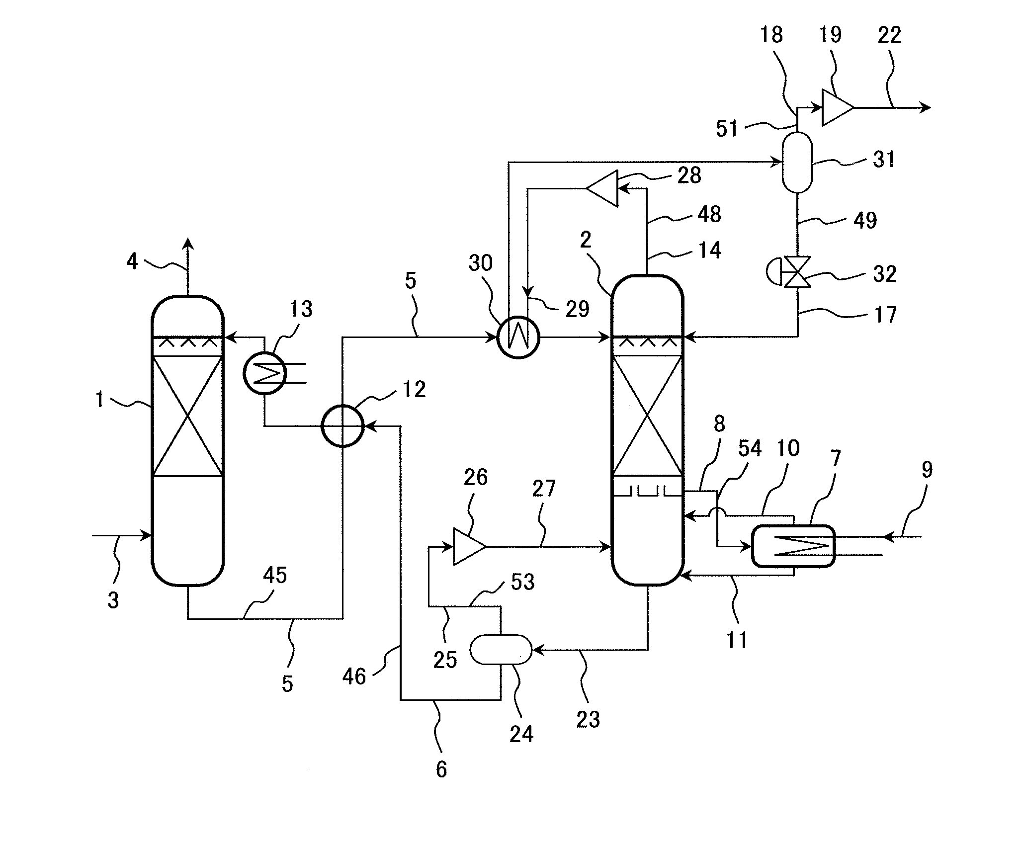
[0030]A first embodiment of the CO2 capture system by chemical absorption according to the present invention will be described with reference to FIG. 1. In FIG. 1, an example will be described in which the outlet gas heat of the regenerator of the CO2 capture system by chemical absorption is recovered and reused for an inlet rich solvent of the regenerator.
[0031]FIG. 1 shows the system configuration of the regenerator and peripheral devices of the CO2 capture system by chemical absorption according to the first embodiment of the present invention.
[0032]The CO2 capture system by chemical absorption according to this embodiment comprises an absorber 1 for removing CO2 contained in exhaust gas by absorbing CO2 by a solvent, and a regenerator 2 for separating CO2 from the solvent that has absorbed CO2 and regenerating the solvent, wherein the solvent is circulated between the absorber 1 and the regenerator 2.
[0033]To explain the CO2 capture system by chemical absorption according to thi...
embodiment 2
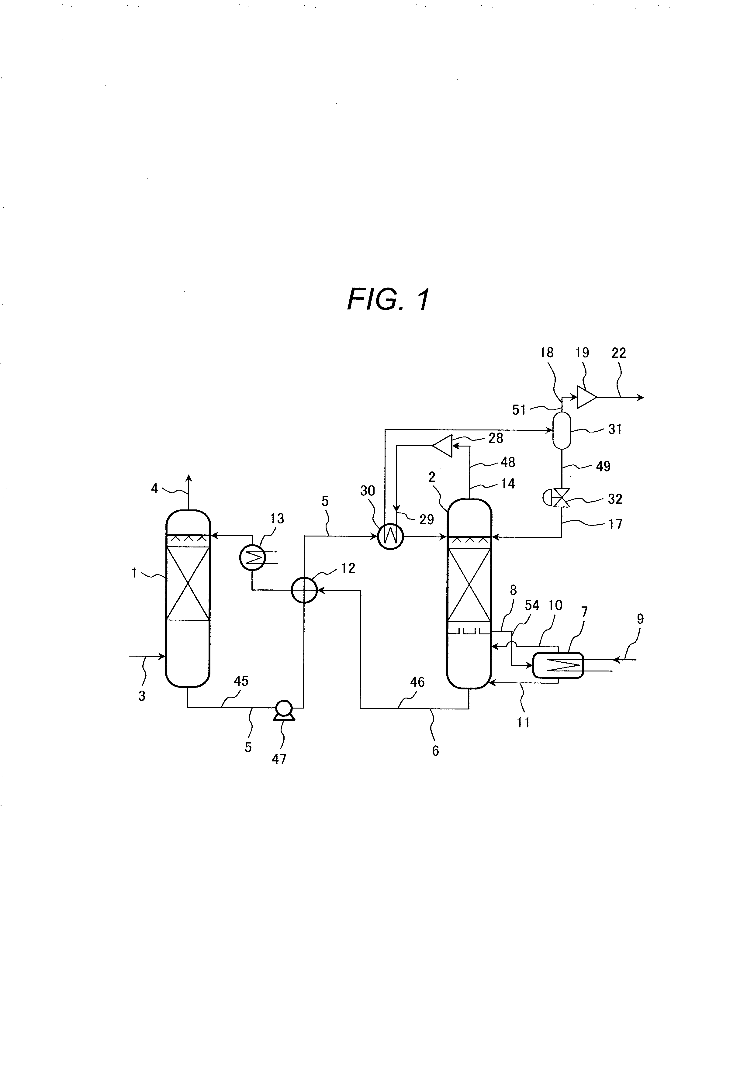
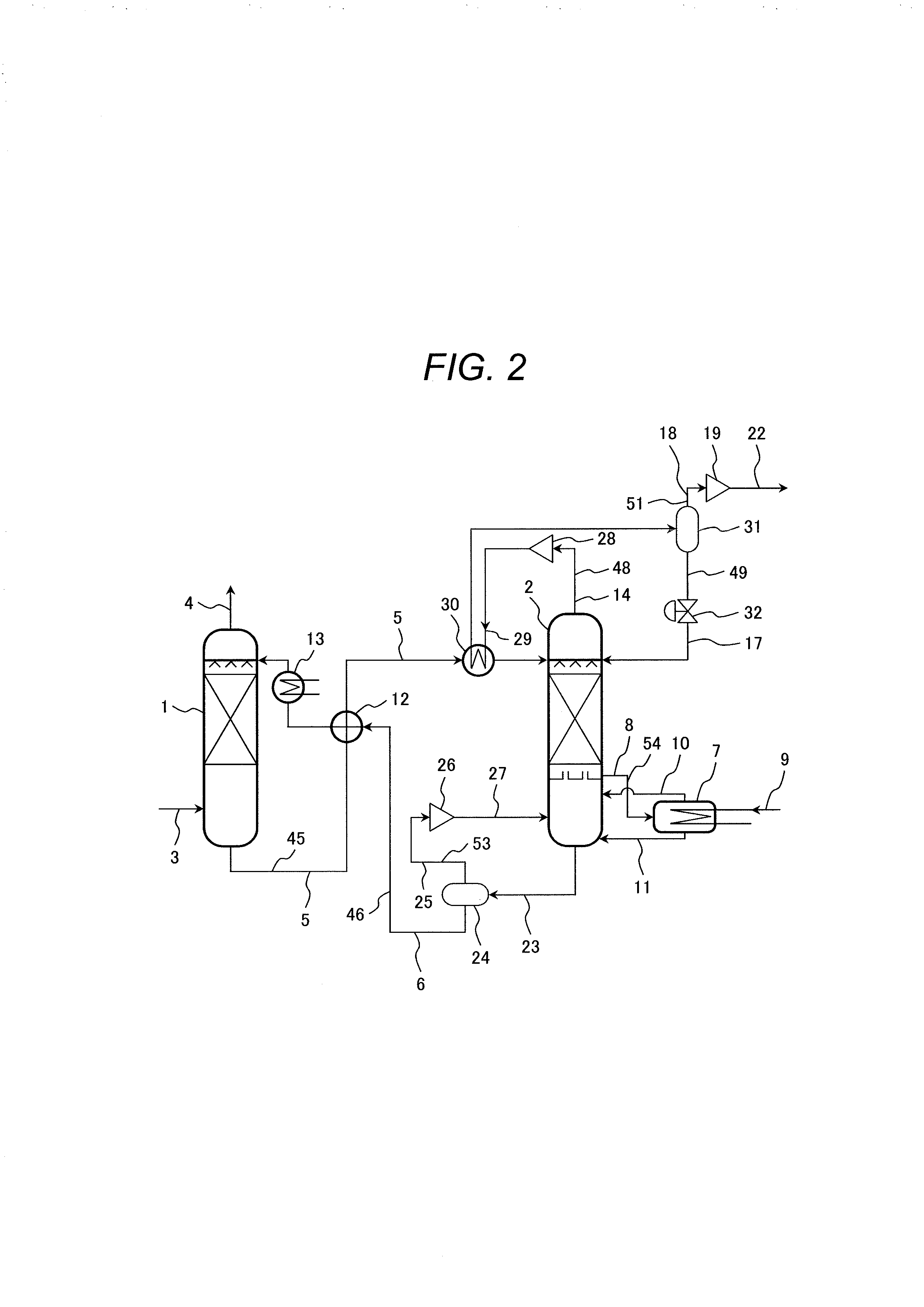
[0054]Next, a second embodiment of the CO2 capture system by chemical absorption according to the present invention will be described with reference to FIG. 2.
[0055]Basic configuration of the CO2 capture system by chemical absorption according to this embodiment shown in FIG. 2 is the same as that of the CO2 capture system by chemical absorption according to the first embodiment shown in FIG. 1. Therefore, description of the configuration common to both systems is omitted and only different parts will be described below.
[0056]FIG. 2 shows an example of the CO2 capture system by chemical absorption that combines the configuration of the CO2 capture system by chemical absorption according to the first embodiment with the VR technique.
[0057]In the CO2 capture system by chemical absorption shown in FIG. 2, the rich solvent 5 that has absorbed CO2 contained in the exhaust gas in the absorber 1 is heated, through the liquid heat exchanger 12 installed along the path of the rich solvent su...
embodiment 3
[0073]Next, a third embodiment of the CO2 capture system by chemical absorption according to the present invention will be described with reference to FIG. 4.
[0074]Basic configuration of the CO2 capture system by chemical absorption according to this embodiment shown in FIG. 4 is the same as that of the CO2 capture system by chemical absorption according to the first embodiment shown in FIG. 1. Therefore, description of the configuration common to both systems is omitted and only different parts will be described below.
[0075]FIG. 4 shows an example of the CO2 capture system by chemical absorption that combines the configuration of the CO2 capture system by chemical absorption according to the first embodiment with the decompression operating method of the reboiler.
[0076]In the CO2 capture system by chemical absorption shown in FIG. 4, pressure of the reboiler 7 is decompressed to become lower than the pressure, 0.15 to 0.2 MPa, of the regenerator and operated. The lean solvent 8 fro...
PUM
Abstract
The CO2 capture system by chemical absorption for removing CO2 from a combustionexhaust gas by a solvent, comprising: an absorber for absorbing CO2 by a solvent, a regenerator for heating a rich solvent absorbed CO2 thereby releasing CO2, a gas exhaust system for discharging gas from the regenerator, a gas compressor installed in the gas exhaust system, a heat exchanger disposed downstream of the gas compressor for exchanging heat between compressed gas and rich solvent to be supplied to the regenerator, a gas-liquid separator disposed downstream of the heat exchanger for separating gas from condensed water, a condensed water supply system for supplying condensed water from the gas-liquid separator to the regenerator, another gas exhaust system for discharging gas containing high-concentration CO2 from the gas-liquid separator, and a compressor disposed downstream of the gas-liquid separator in the another gas exhaust system for pressurizing the gas containing high-concentration CO2.
Description
CLAIM OF PRIORITY [0001]The present application claims priority from Japanese patent application JP 2012-000960 filed on Jan. 6, 2012, the content of which is hereby incorporated by reference into this application.BACKGROUND OF THE INVENTION[0002]1. Technical Field[0003]The present inventions relates to a CO2 capture system by chemical absorption that recovers CO2 from combustionexhaust gas, and in particular, to a CO2 capture system by chemical absorption that reduces energy loss of the CO2 capture system.[0004]2. Background Art[0005]To reduce emission of carbon dioxide (CO2) which causes global warming, technologies for removing CO2 from exhaust gas discharged from plants where fossil fuels are burnt have been being developed. One of those technologies is a CO2 capture system by chemical absorption which recovers CO2 from gas by means of an alkaline solvent.[0006]Basic mechanism of the CO2 capture system by chemical absorption is described in, for example, Japanese Patent Laid-Op...
Claims
Application Information
Patent Timeline
Application Date:The date an application was filed.
Publication Date:The date a patent or application was officially published.
First Publication Date:The earliest publication date of a patent with the same application number.
Issue Date:Publication date of the patent grant document.
PCT Entry Date:The Entry date of PCT National Phase.
Estimated Expiry Date:The statutory expiry date of a patent right according to the Patent Law, and it is the longest term of protection that the patent right can achieve without the termination of the patent right due to other reasons(Term extension factor has been taken into account ).
Invalid Date:Actual expiry date is based on effective date or publication date of legal transaction data of invalid patent.

