Cathode for a Battery

Inactive Publication Date: 2013-07-11
WILDCAT DISCOVERY TECH
View PDF4 Cites 15 Cited by
  • Summary
  • Abstract
  • Description
  • Claims
  • Application Information

AI Technical Summary

Benefits of technology

This patent text describes a new type of electrode for use in electrochemical cells. The electrode has a coating made from an organic coating compound with a conjugated core that is applied to the active electrode material. The coating compound has high conductivity and protects the electrode material from degradation during heating. The electrode is then combined with a binder material and a conductive additive to form a complete electrode. This electrode is useful in making electrochemical cells. The technical effect is the improved performance of electrochemical cells with coated cathode materials.

Problems solved by technology

Further, the overall reaction has a high electrochemical potential.
Despite their widespread use, both types of batteries suffer from certain challenges.
Such comparatively low electrical and ionic conductivity can have the following results in an electrochemical cell: comparatively low power; comparatively low operating voltage; comparatively large underpotential upon discharge; and a comparatively low capacity during a high rate of discharge.
The batteries have comparatively low thermal conductivity as compared to certain other battery materials and such comparatively low thermal conductivity can result in comparatively significant heat generation by the electrochemical cell upon discharge.
Also, certain of these performance improvements come at the expense of reduced energy density.

Method used


Image

  • Cathode for a Battery
  • Cathode for a Battery
  • Cathode for a Battery

Examples


example 1

Fabrication of Conductively Coated Electrodes from Carbon Precursor Materials

[0078]Materials and Synthetic Methods.

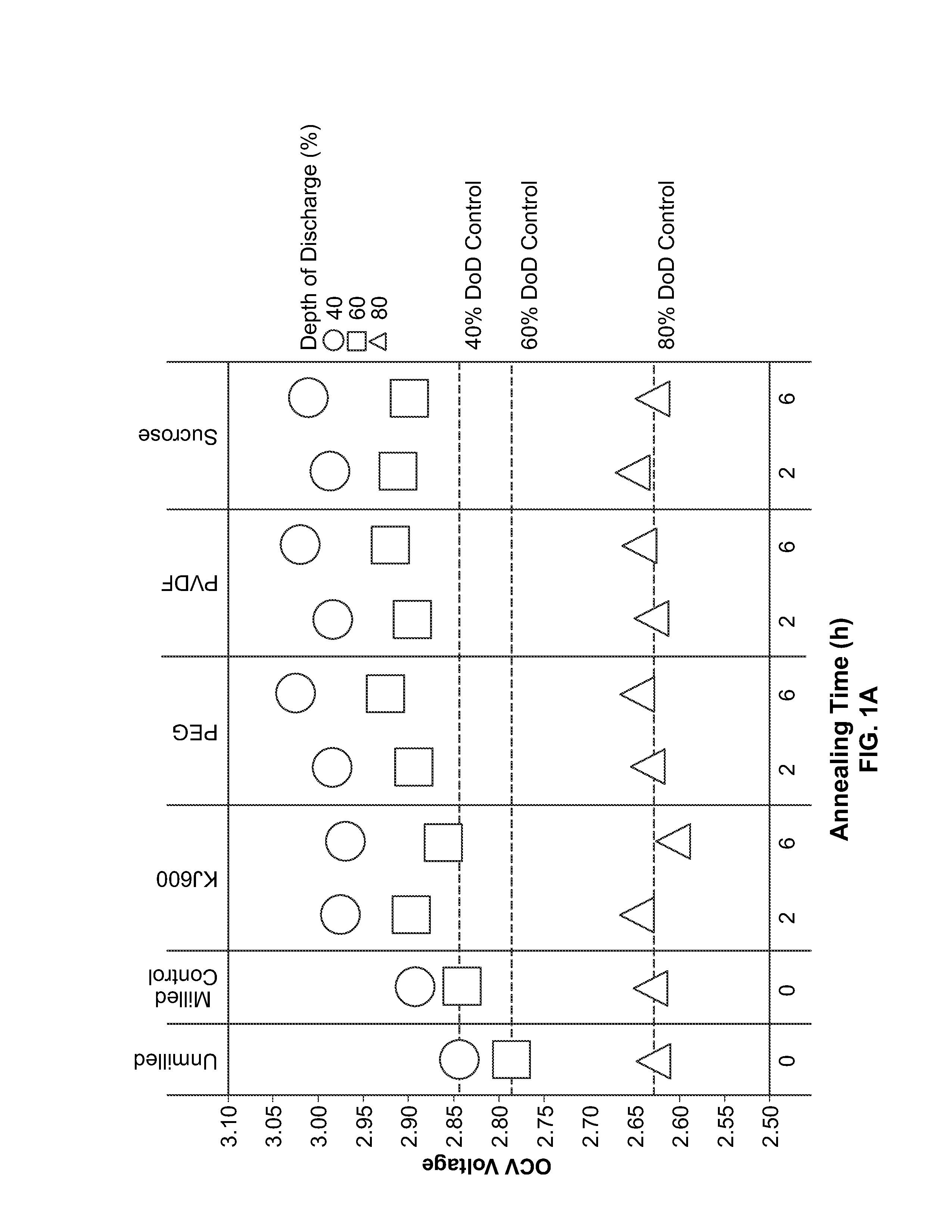
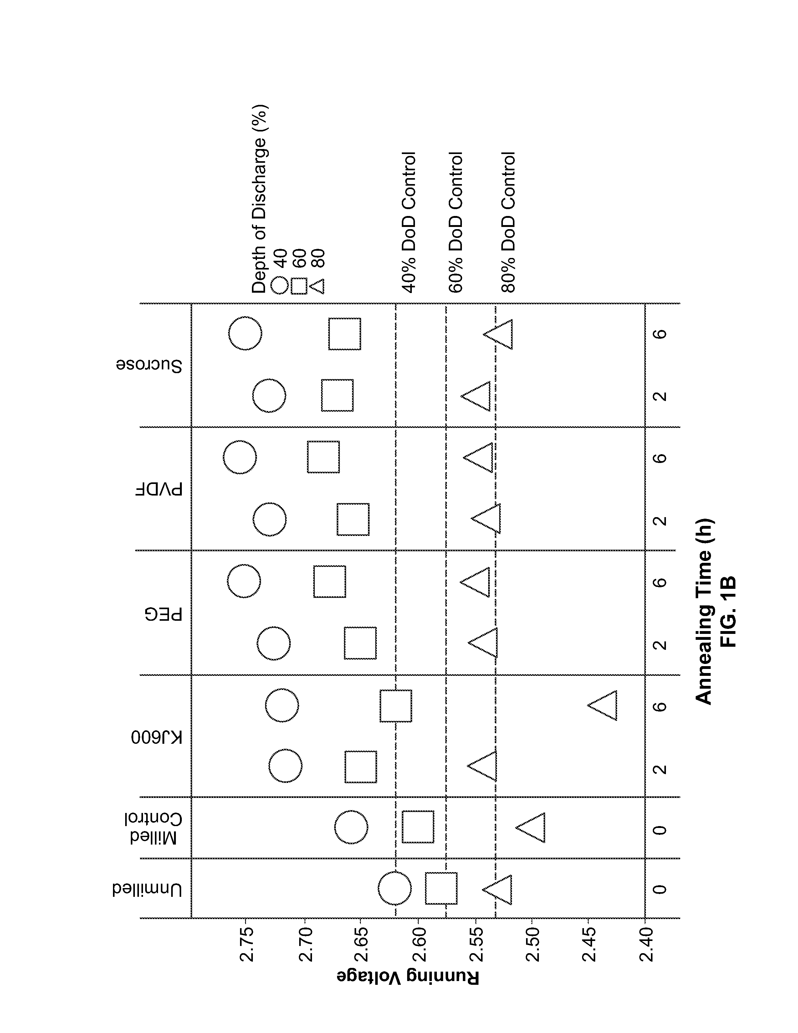
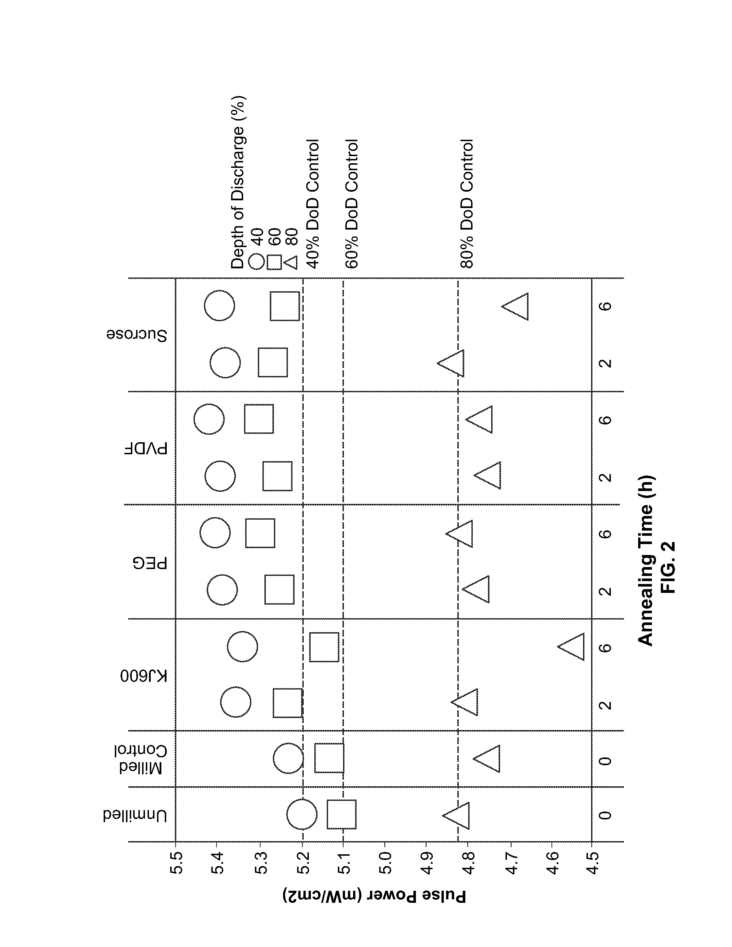
[0079]Carbon-fluoride active material was milled with carbon precursors at medium energy, followed by post annealing. Carbon precursors included KJ600 (carbon black), PEG, PVDF, and sucrose. The carbon precursor loading was 5 wt %. The annealing conditions were 450 and 600 degrees C. for 2 and 6 hours.

example 2

Fabrication of Conductively Coated Electrodes with and without Additive Materials

[0080]Methods were the same as in Example 1, with the following changes:

[0081]Poly(vinylidene fluoride) was used as a carbon precursor; the carbon precursor loading had three conditions (1, 3, 5 wt %); the annealing conditions were 450 and 500 degrees C. at 3, 6 and 12 hours.

example 3

Fabrication of Conductively Coated Electrodes from Conjugated Core Compounds

[0082]Materials and Synthetic Methods.

[0083]All reactions were prepared in a high purity argon filled glove box (M-Braun, O2 and humidity contents <0.1 ppm). Unless otherwise specified, materials were obtained from commercial sources (e.g., Sigma-Aldrich, Advanced Research Chemicals Inc., and Alfa Aesar) and used without further purification.

[0084]Carbon Coating.

[0085]CFx, LMO and LMNO particles were coated with conductive carbon materials through a milling process. Milling vessels were loaded with the base cathode material, conductive carbon coating precursor materials, and solvents. The conductive carbon coating precursor materials are loaded in a range of 0-5 wt %. The vessels were sealed and their contents then milled. After milling, solvents were evaporated at about 60 degrees C. and, in certain embodiments, samples were annealed under flowing N2.

[0086]Electrode Formulation.

[0087]In the case of coated C...


PUM


Abstract

An electrode for an electrochemical cell including an active electrode material and an intrinsically conductive coating wherein the coating is applied to the active electrode material by heating the mixture for a time and at a temperature that limits degradation of the cathode active material.

Description

[0001]This application is a continuation-in-part of co-pending U.S. application Ser. No. 13 / 612,800 filed Sep. 12, 2012 entitled “Cathode for a Battery,” which in turn claims priority to and the benefit of U.S. Provisional Application No. 61 / 533,911 filed Sep. 13, 2011 entitled “Cathode for Metal-Fluoride Battery” and pending U.S. Provisional Application No. 61 / 621,205 filed Apr. 6, 2012 entitled “Cathode for a Battery,” each of which is incorporated herein by reference in its entirety. This application claims priority to and the benefit of each of the above applications.BACKGROUND OF THE INVENTION[0002]The present invention is in the field of battery technology and, more particularly, in the area of using coatings to enhance electrolyte and electrode performance in batteries including metal-fluoride, carbon-fluoride, or oxide-based electrode materials.[0003]One type of battery consists of a negative electrode made primarily from lithium and a positive electrode made primarily from ...

Claims


Application Information

Patent Timeline
IPC IPC(8): H01M4/62H01M4/04H01M4/58
CPCH01M4/366H01M4/382H01M4/5835H01M4/624H01M4/582H01M4/0471Y02E60/122H01M4/08H01M4/505H01M4/525H01M4/583H01M4/0402H01B1/122H01M4/5825H01M4/625Y02E60/10Y02P70/50
Inventor CALDWELL, MARISSAKAYE, STEVENO'NEILL, CORYTONG, WEIKEOGH, DAVID
Owner WILDCAT DISCOVERY TECH
Why Eureka
Try Eureka