Method of recovering a bonding apparatus from a bonding failure

a bonding apparatus and recovery method technology, applied in the field of recovering a bonding apparatus, can solve the problems of undesirable machine downtime prevent the operation of the wire bonder from continuing to operate, and the conventional way of recovering the wire bonder from the bonding failure is not only labour intensive, but time-consuming. , to achieve the effect of reducing the time, facilitating the operation of the electrode, and facilitating the construction of the bonding apparatus

Active Publication Date: 2013-07-18
ASMPT SINGAPORE PTE LTD
View PDF26 Cites 9 Cited by
  • Summary
  • Abstract
  • Description
  • Claims
  • Application Information

AI Technical Summary

Benefits of technology

[0013]Typically, the electrode is used for generating an electric discharge to form a free air ball for bonding with the substrate. By using the same electrode for detaching the semiconductor chip from the wire, the functionality of the electrode may advantageously be enhanced. Moreover, by not having an additional component to detach the semiconductor chip in the bonding apparatus, construction of the bonding apparatus may be simplified.
[0014]Further, the method of recovering the bonding apparatus may additionally comprise the step of the bonding apparatus repositioning the bonding tool with respec...

Problems solved by technology

If the semiconductor chip has not been properly adhered to the substrate, the semiconductor chip may detach from the substrate during wire bonding to cause a bonding failure, especially when the capillary is drawing out a loop of the bonding wire to electrically connect the semiconductor chip with the substrate.
In this case, the detached semiconductor chip would interfere with the...

Method used


Image

  • Method of recovering a bonding apparatus from a bonding failure
  • Method of recovering a bonding apparatus from a bonding failure
  • Method of recovering a bonding apparatus from a bonding failure

Examples


Embodiment Construction

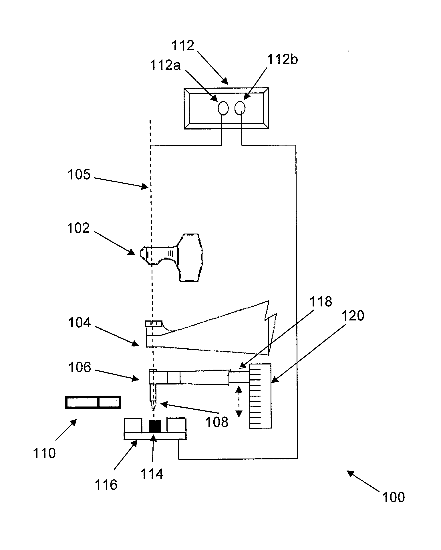
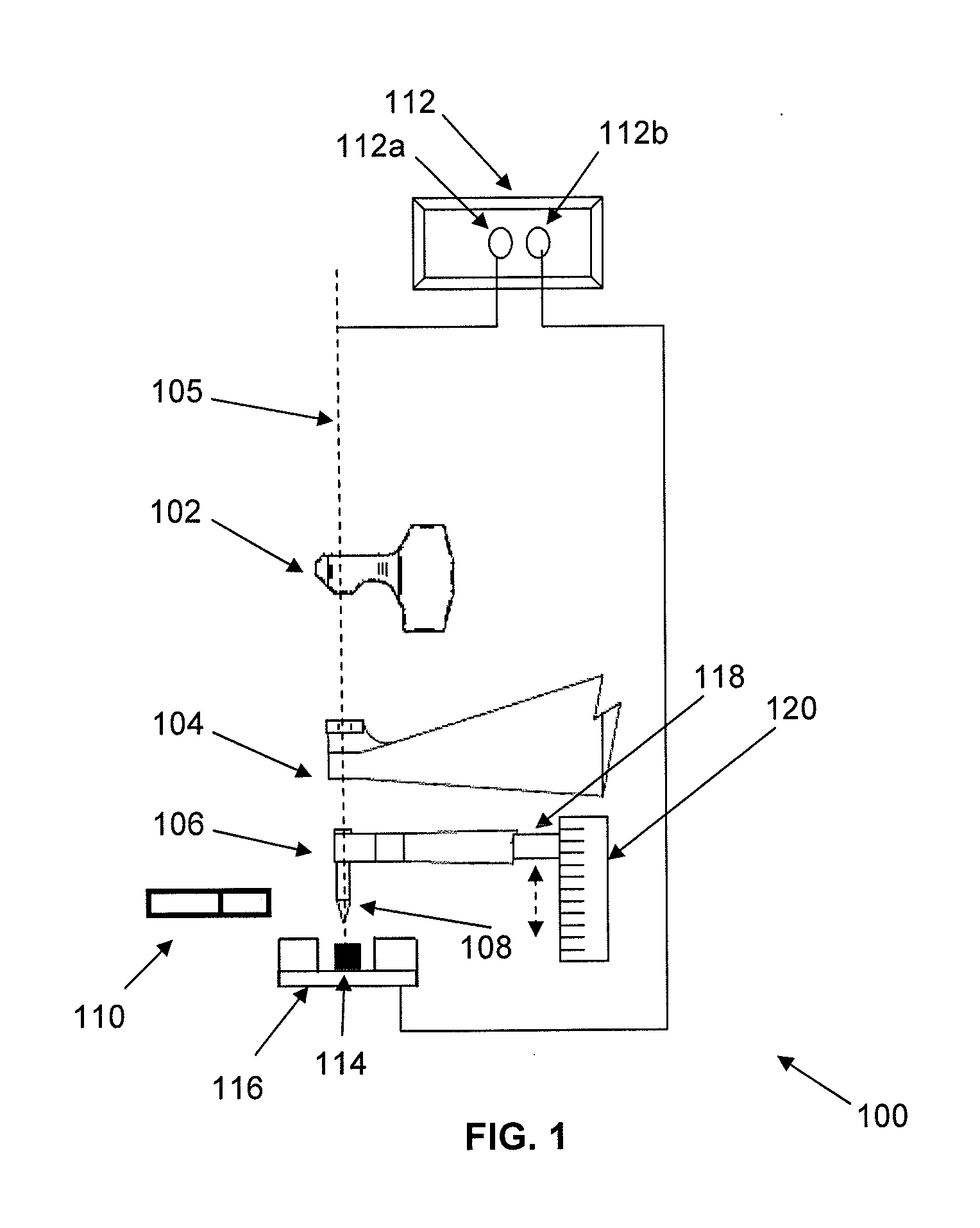
[0025]FIG. 1 shows a bonding apparatus 100 for performing wire bonding. The bonding apparatus 100 comprises: i) an upper clamp 102 and a lower clamp 104 for controlling the movement of a bonding wire 105 fed from a wire spool (not shown) along a wire-feeding path; iii) a transducer horn 106 for producing ultrasonic vibrations during wire bonding; iv) a bonding tool (shown in FIG. 1 as capillary 108) through which the bonding wire 105 is fed during wire bonding; v) an electronic flame-off torch 110 for generating an electric discharge to create a free air ball at a tail end of the bonding wire 105; vi) a contact sensor 112 responsive to contact between objects; and vii) a position sensor (shown in FIG. 1 as an encoder 118) movable relative to a linear scale 120 to determine and measure a position of the capillary 108.

[0026]Before bonding the free air ball of the bonding wire 105 to a semiconductor chip 114 on a substrate (shown in FIG. 1 as a leadframe 116), the contact sensor 112 co...


PUM

PropertyMeasurementUnit
Heightaaaaaaaaaa
Heightaaaaaaaaaa

Abstract

A method of recovering a bonding apparatus from a bonding failure to resume a normal operating state for semiconductor chip fabrication is disclosed. The bonding apparatus comprises: i) a bonding tool for bonding a wire between a semiconductor chip and a substrate; and ii) a position sensor. Specifically, the method comprises the steps of: a) the position sensor determining a position of the bonding tool when the bonding tool contacts a surface to bond the wire to the substrate; b) the bonding apparatus detecting a bonding failure caused by detachment of the semiconductor from the substrate based on the position of the bonding tool; and c) the bonding apparatus detaching the semiconductor chip from the wire.

Description

TECHNICAL FIELD OF THE INVENTION[0001]The present invention relates to a method of recovering a bonding apparatus during a bonding failure to resume a normal operating state for semiconductor chip fabrication.BACKGROUND OF THE INVENTION[0002]Bonding apparatus are used in semiconductor assembly and packaging. An example of a bonding apparatus is a wire bonder, which makes electrical wire connections between electrical contact pads of semiconductor chips and a substrate—a process which is known as wire bonding. Specifically, bonding wire is fed from a wire spool to a bonding tool (e.g. a capillary) to make the electrical wire connections between the semiconductor chips and the substrate during wire bonding.[0003]One method of wire bonding uses a ball bond and involves a series of steps, as follows: i) melting a length of bonding wire held by the capillary to produce a free air ball; ii) lowering the free air ball to an electrical contact pad of a semiconductor chip; and iii) welding t...

Claims


Application Information

Patent Timeline
IPC IPC(8): B23H1/00B23K1/018
CPCH01L2224/78268B23K20/007H01L24/78H01L24/85H01L2224/48091H01L2224/78H01L2224/78301H01L2224/85181H01L2224/859H01L2924/00014H01L2924/01327H01L24/48H01L2224/45099H01L2224/484H01L2224/85205H01L2924/12036
Inventor LEE, WAI WAHLI, JUN FENGWONG, WEI BOONTAN, SOO KIN KENNY
Owner ASMPT SINGAPORE PTE LTD
Why Eureka
Try Eureka