Respiratory valve apparatus

a technology of respiratory valve and valve body, which is applied in the direction of breathing mask, breathing protection, other medical devices, etc., can solve the problems of insufficient efficacy of stale expired gas venting from the user's respiratory system, user's risk of re-breathing a substantial proportion of expired air and asphyxiation, and prior art exhibits further inherent limitations

Active Publication Date: 2013-07-25
VENTIFIC HLDG
View PDF6 Cites 27 Cited by
  • Summary
  • Abstract
  • Description
  • Claims
  • Application Information

AI Technical Summary

Benefits of technology

[0007]Preferably the exhaust poll includes a plurality of substantially parallel slots spaced circumferentially around the valve body at the exhaled gas flow passage. More preferably the plurality of slots are staggered in length. Even more preferably the plurality of slots are each longitudinally tapered in thickness being progressively narrower in an upstream direction.
[0008]Preferably the flexible membrane is a flexible synthetic polymeric film of a thickness less than 0.1 mm. More preferably the synthetic polymeric film is polyethylene of a thickness less than 50 μm. Preferably the flexible membrane is a sock-like structure having an outer surface shaped substantially complementary to an inner cylindrical wall of the valve body against which it seals. More preferably the sock-like structure is tapered in shape with the flexible membrane becoming progressively smaller in circumference from its open end to its closed end. Alternatively the sock-like structure is tapered in shape with the flexible membrane becoming progressively larger in circumference from its open end to its c...

Problems solved by technology

An absence of means to physically prevent reverse flow of expired gas back towards the pressure source means that some fraction of a user's exhaled air may accumulate within the pressure source and thereby be re-inhaled during subsequent inhalation or lung reinflation.
It is apparent therefore that the lower the therapeutic pressure. the less effective is the venting of stale expired gas from a user's respiratory system.
Prolonged use below this minimum pressure puts the user at risk of rebreathing a substantial proportion of their expired air and asphyxiation if both nose and mouth breathing routes are covered by a. well-fitting oronasal mask, for example.
It is evident that the prior art exhibits further inherent limitations depending on operating circumstances.
When breathable gas exits the vents of the user interface, it typically creates noise which may irritate the user or their bed partner.
This ma...

Method used


Image

  • Respiratory valve apparatus
  • Respiratory valve apparatus
  • Respiratory valve apparatus

Examples


Embodiment Construction

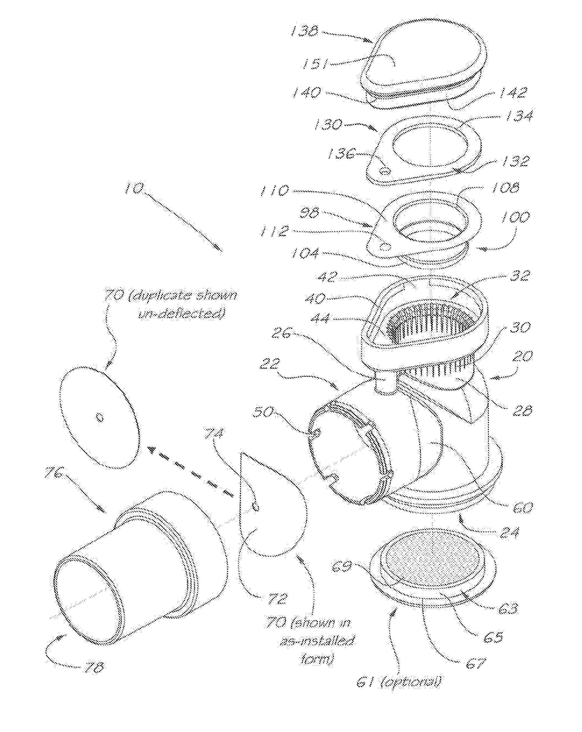
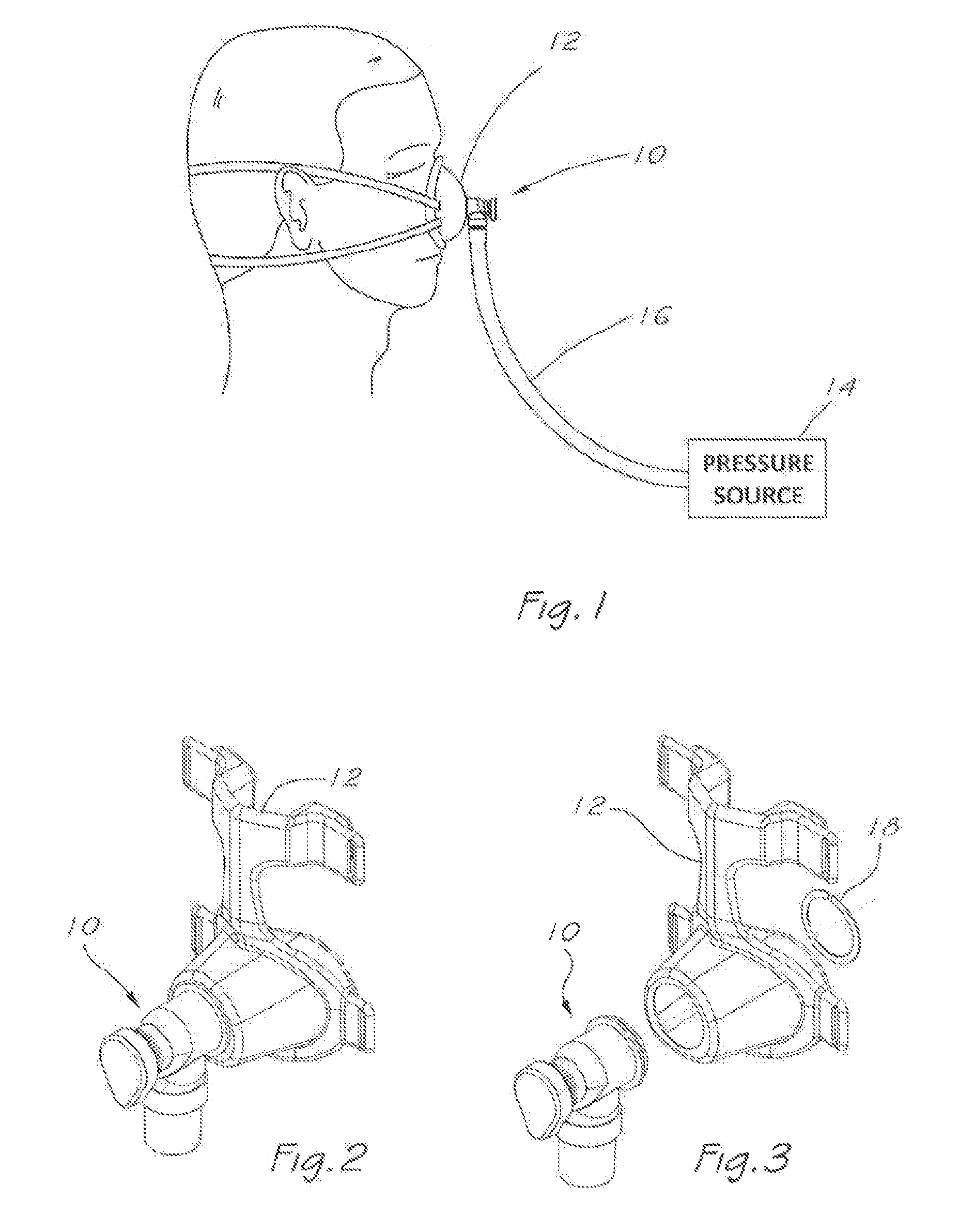
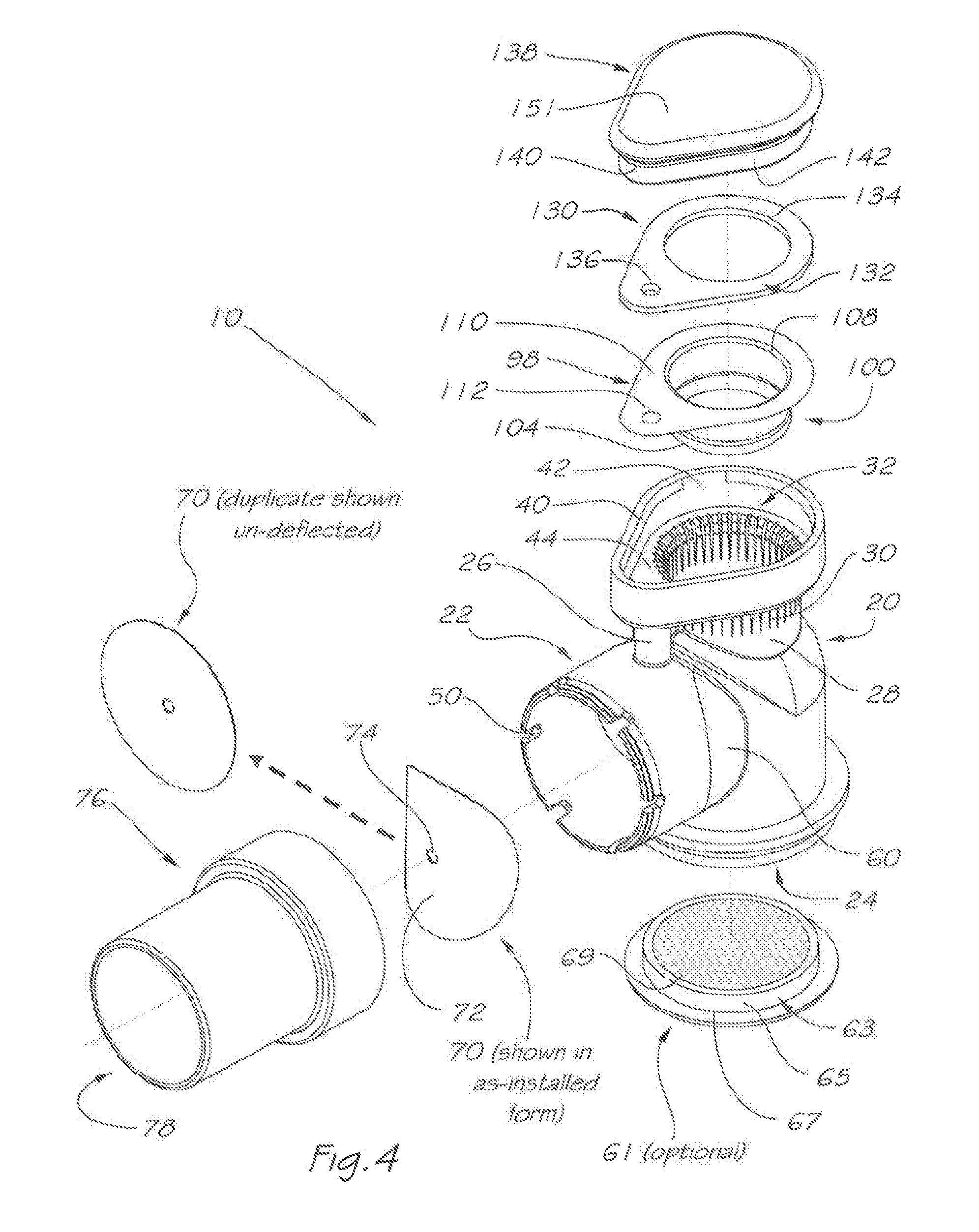
[0064]A first embodiment of a respiratory valve apparatus according to a first aspect of the present invention is shown in FIGS. 1 to 7. FIG. 1 shows the apparatus 10 in use in a system for providing respiratory therapy. Apparatus 10 is coupled or sealably secured to a mask or user interface 12 covering the nose of a user, and is fed with a pressurised flow of breathable gas from a pressure source comprising gas flow generator 14 and delivery tube 16, whereby breathable gas is delivered to the airway of the user.

[0065]It will be appreciated by those skilled in the art that although a nasal user interface is depicted here, alternatives such as an oronasal, oral appliance tracheostomy or endotracheal tube may also be applicable.

[0066]The user may be an individual undergoing respiratory therapy, and the breathable gas may be enriched with a therapeutic gas, such as oxygen, or include a therapeutic agent, and be in a variety of forms, such as a nebulized mist, powder or gas.

[0067]FIG. 2...


PUM


Abstract

The invention relates to a pressure responsive respiratory valve apparatus for enabling positive pressure from a source of pressure to be applied to a user's airway, and allowing ingress of a breathable gas from an inlet port into a user's airway during inhalation and egress of expired tidal volume of air from the user's respiratory system to an exhalation port during exhalation. The invention minimises rebreathing of expired gas and optimizes delivery of pressurised breathable gas by venting gas only during exhalation, as well as addressing important user considerations including minimizing noise, pressure swine, and size.

Description

FIELD OF THE INVENTION[0001]The present invention relates broadly to a respiratory valve apparatus. The present invention is in the field of positive pressure respiratory therapy such as nasal CPAP or positive pressure ventilation, as may be applied to a user through a user interface, such as a nasal mask, oronasal mask, nasal prongs or suitable invasive means, such as tracheostomy or endotracheal tube.TECHNICAL BACKGROUND[0002]Positive pressure respiratory therapies, such as continuous positive airway pressure (CPAP) therapy, and intermittent positive pressure ventilation therapy (IPPV), are commonly administered for the treatment of a wide range of respiratory conditions, including central and obstructive sleep apnea. (OSA), chronic obstructive pulmonary disease (COPD), restrictive respiratory insufficiency and acute respiratory failure (ARF). Acute and chronic life support systems also make use of positive 15 pressure respiratory therapies using volume or pressure controlled cycl...

Claims


Application Information

Patent Timeline
IPC IPC(8): A61M16/20A61M16/06A61M16/10A61M16/00
CPCA61M16/06A61M16/1045A61M16/20A61M16/0666A61M16/206A61M16/0057A61M16/201A61M16/0616A61M16/0633A61M16/0825A61M16/0816A61M2202/0225A61M16/208A61M2202/0085A61M16/0875
Inventor HALLETT, MICHAEL DAVIDGUNARATNAM, MICHAEL KASSIPIPILLAIGREGERSEN, ALLAN NILS
Owner VENTIFIC HLDG
Why Eureka
Try Eureka