Composite rod, manufacturing method and tool

Active Publication Date: 2013-07-25
AIRBUS OPERATIONS SL
View PDF5 Cites 9 Cited by
  • Summary
  • Abstract
  • Description
  • Claims
  • Application Information

AI Technical Summary

Benefits of technology

[0012]and between the two bodies the rod comprises a conductor material, preferably at least one layer of copper foil. In order to accomplish with the requirement that electrical energy must be conducted across t

Problems solved by technology

In addition, the supported loads of the rods are the cyclic loads of each opening/close of the door on each landing and take-off operation, and therefore the fatigue loads are critical.
Besides, the MLGD and the Belly Fairing are identified as high risk of lightning strike.
The main t

Method used


Image

  • Composite rod, manufacturing method and tool
  • Composite rod, manufacturing method and tool
  • Composite rod, manufacturing method and tool

Examples


Embodiment Construction

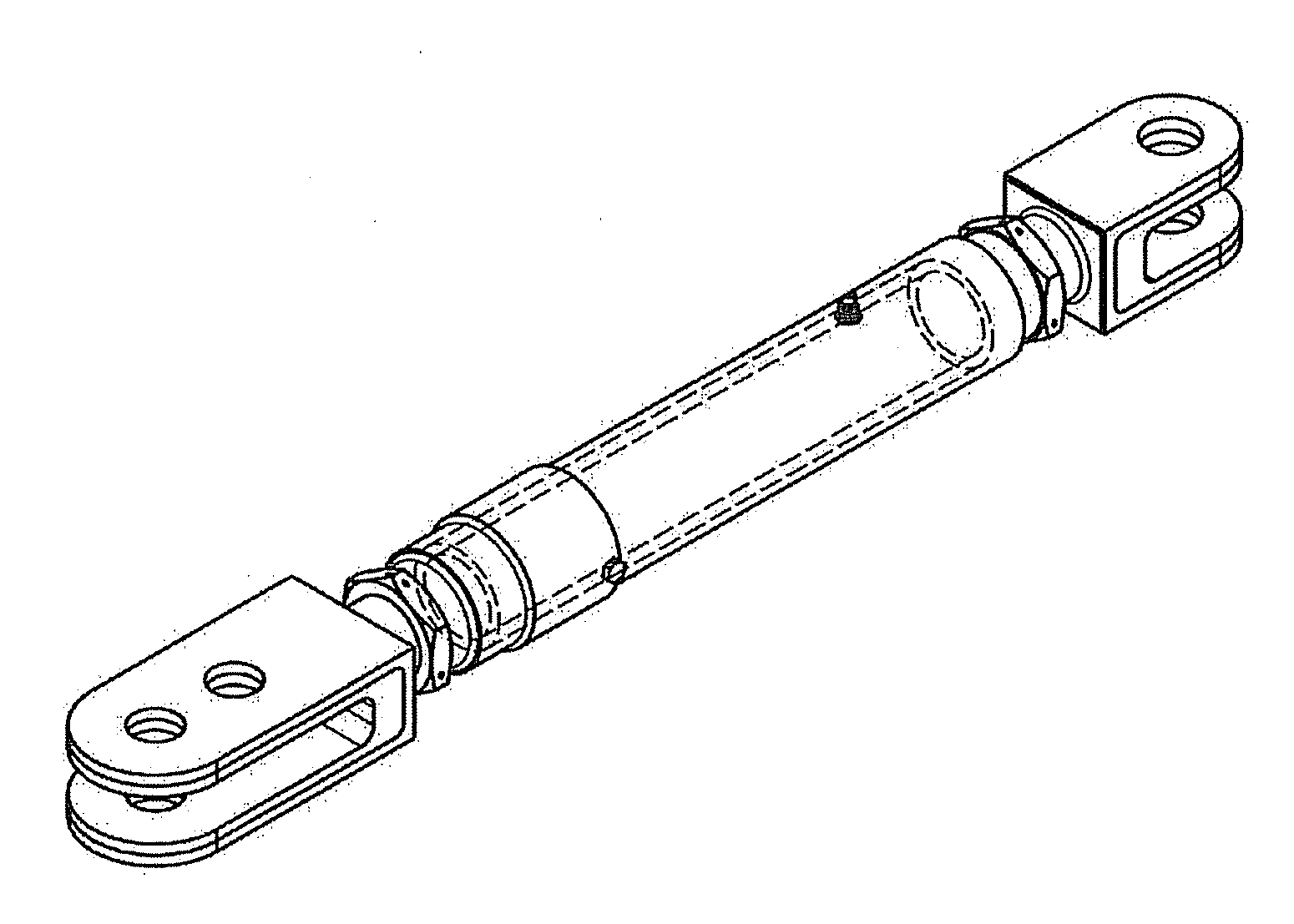
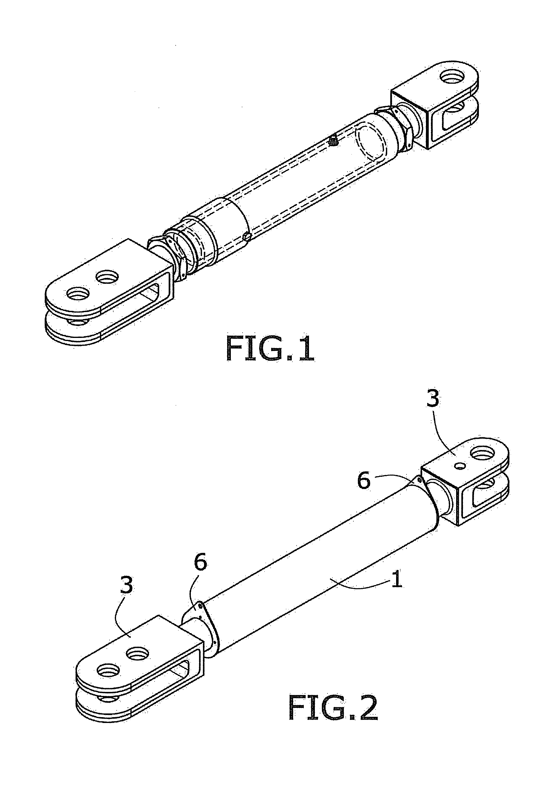
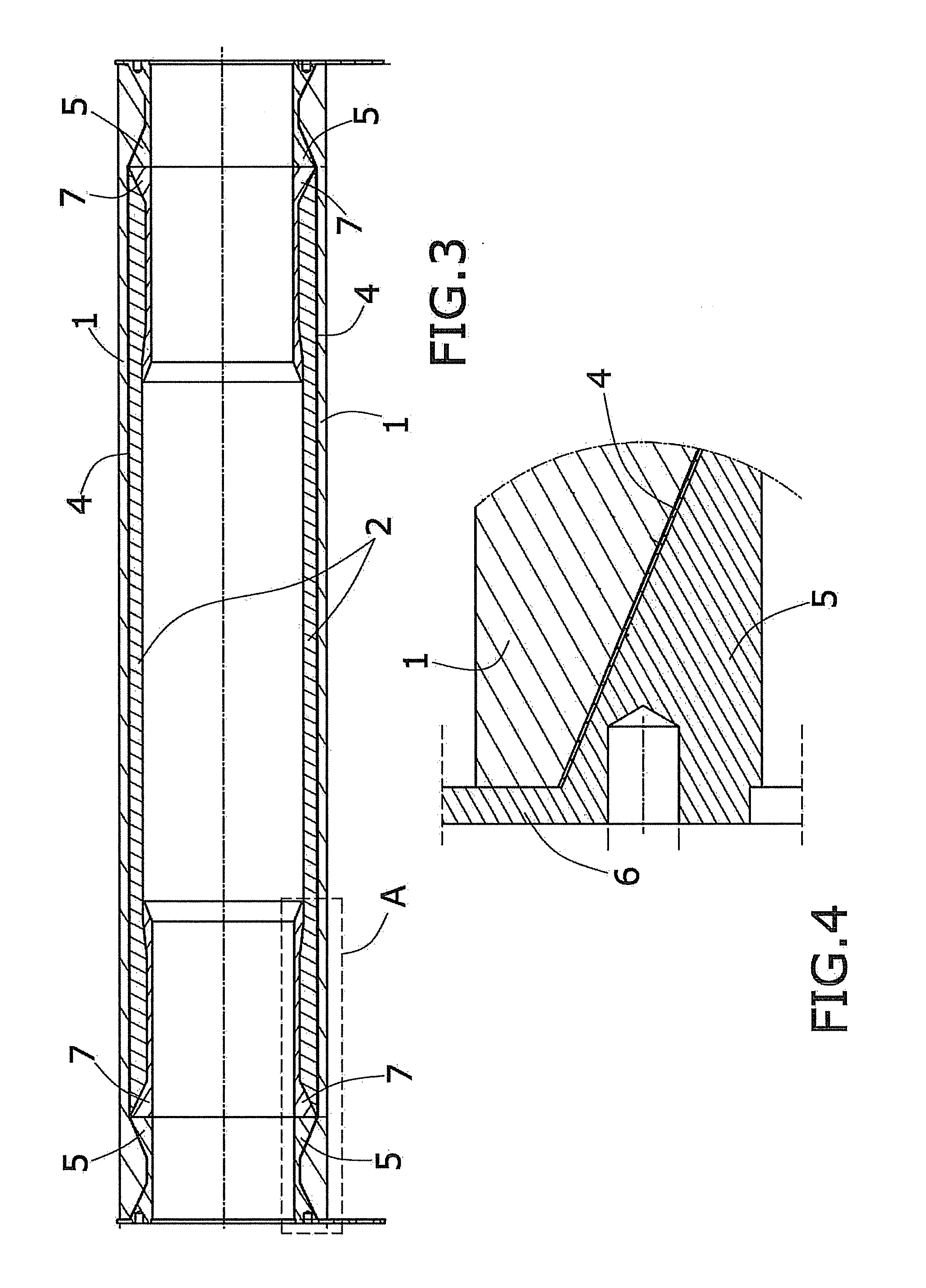
[0006]The objects of the invention are achieved by means of a composite rod to keep two elements apart a determined distance in accordance with claim 1, a single shot manufacturing method for obtaining a hollow rod structure in accordance with claim 13 and a tool to be used in the single shot manufacturing method in accordance with claim 15. The particular embodiments of the invention are defined in the dependent claims.

[0007]Without limiting the scope of use of the invention to aircrafts and generalizing to any other use requiring two elements apart a determined distance carrying the loads between them, such as railways, industrial premises, etc., the present invention presents in a first aspect a composite rod, wherein the rod comprises:[0008]two hollow bodies, an outer body and an inner body, each one of the two bodies able to withstand the loads, providing a double path load; These two hollow bodies, one inside the other, provide a fail-safe design to the whole structure in orde...


PUM

PropertyMeasurementUnit
Fractionaaaaaaaaaa
Pressureaaaaaaaaaa
Angleaaaaaaaaaa

Abstract

The present invention describes composite rods keeping two elements apart a determined distance carrying the loads between them, such as railways, industrial premises, etc. Besides, the manufacturing method thereof and the tool involved in this process are also described.

Description

CROSS-REFERENCE TO RELATED APPLICATION[0001]This U.S. non-provisional patent application claims priority to European Patent Application No. 11382391.8 filed on Dec. 22, 2011, the entire contents of which are hereby incorporated by reference.FIELD OF THE INVENTION[0002]The present invention describes composite rods, the manufacturing method thereof and the tool involved in this process. The invention belongs to the field of fibre reinforced plastic structures for the purposes of keeping two elements apart a determined distance carrying the loads between them.BACKGROUND OF THE INVENTION[0003]Rods are structures usually used by engineers to keep two elements apart a determined distance (fixed or variable) carrying the loads between them. Metallic rods and struts are the main elements of many designs: they support structural or system elements and ensure even load distribution within structures. Usually, the connected structures are equipped with ball bearings to avoid the transmission ...

Claims


Application Information

Patent Timeline
IPC IPC(8): F16M13/02B32B37/00B32B37/02
CPCB64C1/06B32B37/0053B32B37/02F16C2326/43F16C7/02B29C33/485F16M13/02
Inventor QUINTANA RIO, ANDRES
Owner AIRBUS OPERATIONS SL
Why Eureka
Try Eureka