LED 3D curved lead frame of illumination device

Inactive Publication Date: 2013-07-25
LONGWIDE TECH
View PDF6 Cites 10 Cited by
  • Summary
  • Abstract
  • Description
  • Claims
  • Application Information

AI Technical Summary

Benefits of technology

[0002]This invention is to separately produce the complicated 3D curved structure and LED 3D curved lead frame, spread the curved luminous circuit into plane circuit, and utilize conductive metal charge tape to produce lead frames of single layers and accumulate into banded structure of multilayer lead frame, and install LED chip on the installation seat and form LED flat lead frame, then use ductility and plastic deformation features of conductive

Problems solved by technology

In addition, the angle of projection light of LED illumination member is likely more than 100 conicity, unless the reflector has enough length or special design, that is, part of light will be directly projected to outside, and a part of light will be projected on the reflector, and multiple reflection will also cause attenuation of illumination, and the irregular reflection surface required by the reflector will result in more difficulty and cost.
It is known from numerous signal pins of illumination module that, precise multilayer PCB must be used to install these numerous LEDs, and the control signal of the baseplate should be also used to enable the annular display surface to accomplish dynamic display effect, but it is still limited by PCB and unable to obtain the display function of 3D curved surface.
The flexible PCB is equipped with plural full-color LED units to form one matrix, and the signal connection among modularized LED display boards is used to form large-scale LED display system; this Prima Facie Case adopts full-color LED chip unit containing drive mechanism, so the display function can be acquired only from the flexible board, but it is still limited by flexible PCB, causing that the display f

Method used


Image

  • LED 3D curved lead frame of illumination device
  • LED 3D curved lead frame of illumination device
  • LED 3D curved lead frame of illumination device

Examples


embodiment 1

is LED 3D curved lead frame of the present invention applied in white light luminaire with function of illumination curved surface.

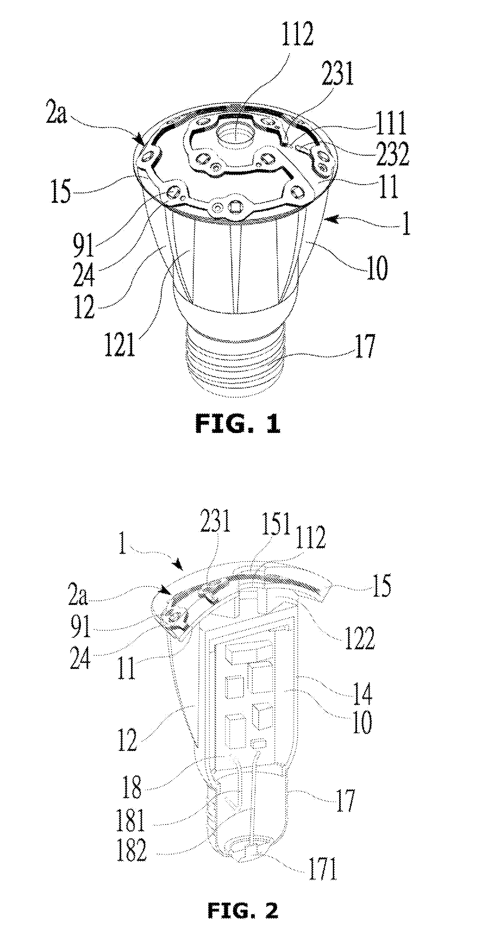
[0070]Please refer to FIG. 1 and FIG. 2, the external structure diagram of white light luminaire of Embodiment 1 of the present invention. Luminaire 1 contains aluminum alloy main body 10; illumination curved surface 11, heat dissipating fin 12, LED 3D curved lead frame 2a, spiral joint 17, white light LED chip 91, and transparent package 15; when the luminaire in this embodiment is installed on the ceiling. The spiral joint 17 is located at the top; illumination curved surface 11 is located at the bottom, and illumination curved surface 11 becomes spherical shape and connects with heat dissipating fin 12. LED 3D curved lead frame 2a is installed on illumination curved surface 11. The surface has transparent package 15, which is used to protect LED 3D curved lead frame 2a and LED chip 91, and 12 white light LED chips 91 is installed in installation seat ...

embodiment 2

is LED 3D curved lead frame of the present invention that is applied in multicolor luminaire with illumination curved surface function.

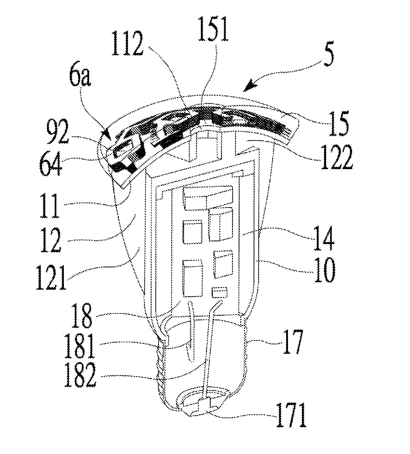
[0083]Please refer to FIG. 4 and FIG. 5, external structure diagram of multicolor luminaire of the present invention Embodiment 2. Multicolor luminaire 5 contains aluminum alloy main body 10, illumination curved surface 11, heat dissipating fin 12, LED 3D curved lead frame 6a, spiral joint 17, multicolor LED chip 92 and transparent package 15; when the luminaire of this embodiment is installed on the ceiling, spiral joint 17 is located at the top, illumination curved surface 11 is located at the bottom, and illumination curved surface 11 becomes spherical shape, which is connected with heat dissipating fin 12. LED 3D curved lead frame 6a is installed on illumination curved surface 11. The surface has transparent package 15 that is used to protect LED 3D curved lead frame 6a and multicolor LED chip 92; and multicolor LED chip 92 is installed in instal...

embodiment 3

is LED 3D curved lead frame of the present invention that is applied in curved or spherical multicolor advertising boards and illumination device.

[0098]Please refer to FIG. 7(A), FIG. 7(B), FIG. 8 and FIG. 9, multicolor LED curved display advertising board module structure diagram of Embodiment 3 of the present invention. Multicolor advertising board module 7 contains aluminum alloy main body curved surface 71 and LED 3D curved lead frame 8a. The circuit of this embodiment is 16×16 series connection multicolor LED chip 93. LED 3D curved lead frame 8a takes banded structure to arrange in matrix shape on curved surface 71 under series connection. Curved surface 71 of aluminum alloy main body is equipped with through hole 711, which enables power contact 831(V) and power contact 834(G) as well as timing sequence contact 832(C) and signal contact 833(S) of LED 3D curved lead frame 8a to be connected to controller and image decoder of display system. Chip 93 is the integrated package chi...


PUM


Abstract

This invention relates to separately produce the complicated 3D curved structure and LED 3D curved lead frame to meet the demand of the complicated curved surface illumination of illumination device. First of all, draw illumination circuit with banded structure of multilayer lead frame on 3D illumination complicated curved surface, then spread these curved circuit into plane circuit, dismantle the banded structure of multilayer lead frame of circuit into circuit pattern of single layers, use process the prototype of circuit patterns of each layer with conductive metal charge tape, and produce the prototype of banded structure of multilayer conductive frame through repeated accumulation of multi-disc charge tapes, and install the LED chip on the installation seat to get LED flat lead frame, then flex the conductive metal into LED 3D curved lead frame with jig and paste on the luminous curved surface, and package them together with transparent material, for example, curved decorative lighting, spherical display advertising board, etc.; this method offers more flexibility for structure and aesthetic design, and fully utilizes the high heat dissipation capacity of main body of metal part.

Description

CROSS-REFERENCE[0001]The current application claims a foreign priority to the patent application of Taiwan No. 101101175 filed on Jan. 12, 2012.SUMMARY OF THE INVENTION[0002]This invention is to separately produce the complicated 3D curved structure and LED 3D curved lead frame, spread the curved luminous circuit into plane circuit, and utilize conductive metal charge tape to produce lead frames of single layers and accumulate into banded structure of multilayer lead frame, and install LED chip on the installation seat and form LED flat lead frame, then use ductility and plastic deformation features of conductive metal to flex into LED 3D curved lead frame, and paste on the complicated curved surface of the metal part, package into one body with transparent materials such as hardened resin or silica gel, for example, decorative lighting, curved display advertising board and other curved illumination devices; this method offers more flexibility for structure and aesthetic design, and...

Claims


Application Information

Patent Timeline
IPC IPC(8): F21V21/00F21V29/00F21V15/01
CPCF21K9/135F21Y2101/02F21V29/74F21V15/01F21V21/00F21Y2111/004F21K9/232F21Y2107/20F21Y2115/10F21Y2113/13F21Y2113/17H05K1/189H05K3/202H05K2201/0397H05K2201/09263H05K2201/10106F21V23/001F21V29/773F21K9/238H05K1/181
Inventor CHIEN, HUAN-JANTSAI, TSUNG-HONG
Owner LONGWIDE TECH
Why Eureka
Try Eureka