
Chemical oxygen generator with core channel tube for an emergency oxygen device

Active Publication Date: 2013-08-01
SAFRAN AEROTECHNICS
View PDF15 Cites 9 Cited by
  • Summary
  • Abstract
  • Description
  • Claims
  • Application Information

AI Technical Summary

Benefits of technology

The chemical oxygen generator is designed to improve the production of oxygen by using a hollow tube around a solid oxygen source. This design increases the surface area of the solid oxygen source and provides a path for heat transfer, resulting in a more constant chemical reaction and faster startup after ignition. Additionally, a flow control unit can be integrated into the housing for controlling the flow rate and pressure of the oxygen generated by the chemical reaction. The design of the chemical oxygen generator is compact.

Problems solved by technology

A first problem associated with such emergency oxygen devices utilizing a chemical oxygen generator is the procedure of starting the chemical reaction which requires a specific interaction of mechanical and pyrolytic components.
This interaction is prone to misuse and maloperation and can not be adapted to modern cabin control systems with regard to maintenance and safety conditions.
A second problem associated with such emergency oxygen devices utilizing chemical oxygen generators is the non-constant production of oxygen as a result of the chemical reaction.
Hereafter, in a first phase of the chemical reaction, only a small volume of oxygen is produced which is in particular unfavorable because the aircraft may at this time be in high altitude flight level wherein a decompression situation within the cabin requires a high amount of oxygen to be supplied to the passengers to maintain their vital functions.
However, in this second stage the aircraft may have descended to a low altitude flight level in order to relieve the decompression situation and the passenger may only require a small amount of oxygen at this flight level.
However, given a situation where the decompression situation occurs in a long distance to the nearest suitable airport, the aircraft may expect a long flight time until it reaches the airport and thus it would be ideal to supply a small amount of oxygen over a long time to the passenger.
However, a major draw back of these systems is the need to handle high pressures within the emergency oxygen system with requires continuous safety checks and maintenance of the system to ensure proper function of the system.
Further, such oxygen pressure tanks must be completely sealed in order to hold the required amount of oxygen inside and a leakage of oxygen out of such tanks is very dangerous in that the air inside the aircraft may be enriched with oxygen and thus the risk of fire on board the aircraft is increased.
A further draw back of such systems is the significant weight of such a pressure tank which is caused by the wall thickness required for bearing the high inner pressure inside the tank.
However, this causes significant disadvantages in the system.
Secondly, such increase of pressure inside the chemical oxygen generator will inadvertently influence the chemical reaction and may result in a reduction of the reaction.
This, however, makes its difficult to control the oxygen flow and in particular produces the risk that the chemical reaction is stopped or reduced to a degree which is not sufficient for the production of enough oxygen for the passenger.

Method used


Image

  • Chemical oxygen generator with core channel tube for an emergency oxygen device
  • Chemical oxygen generator with core channel tube for an emergency oxygen device
  • Chemical oxygen generator with core channel tube for an emergency oxygen device

Examples


first embodiment

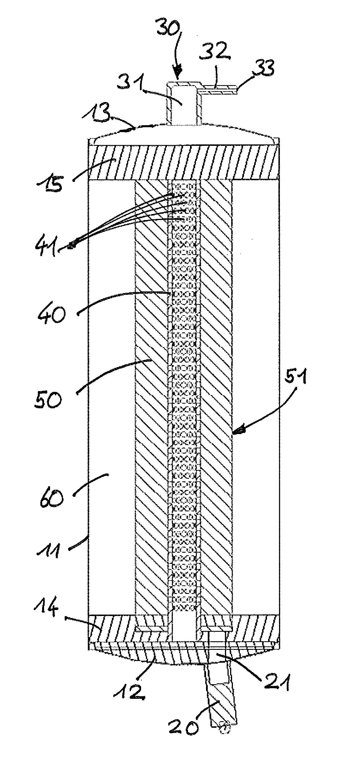
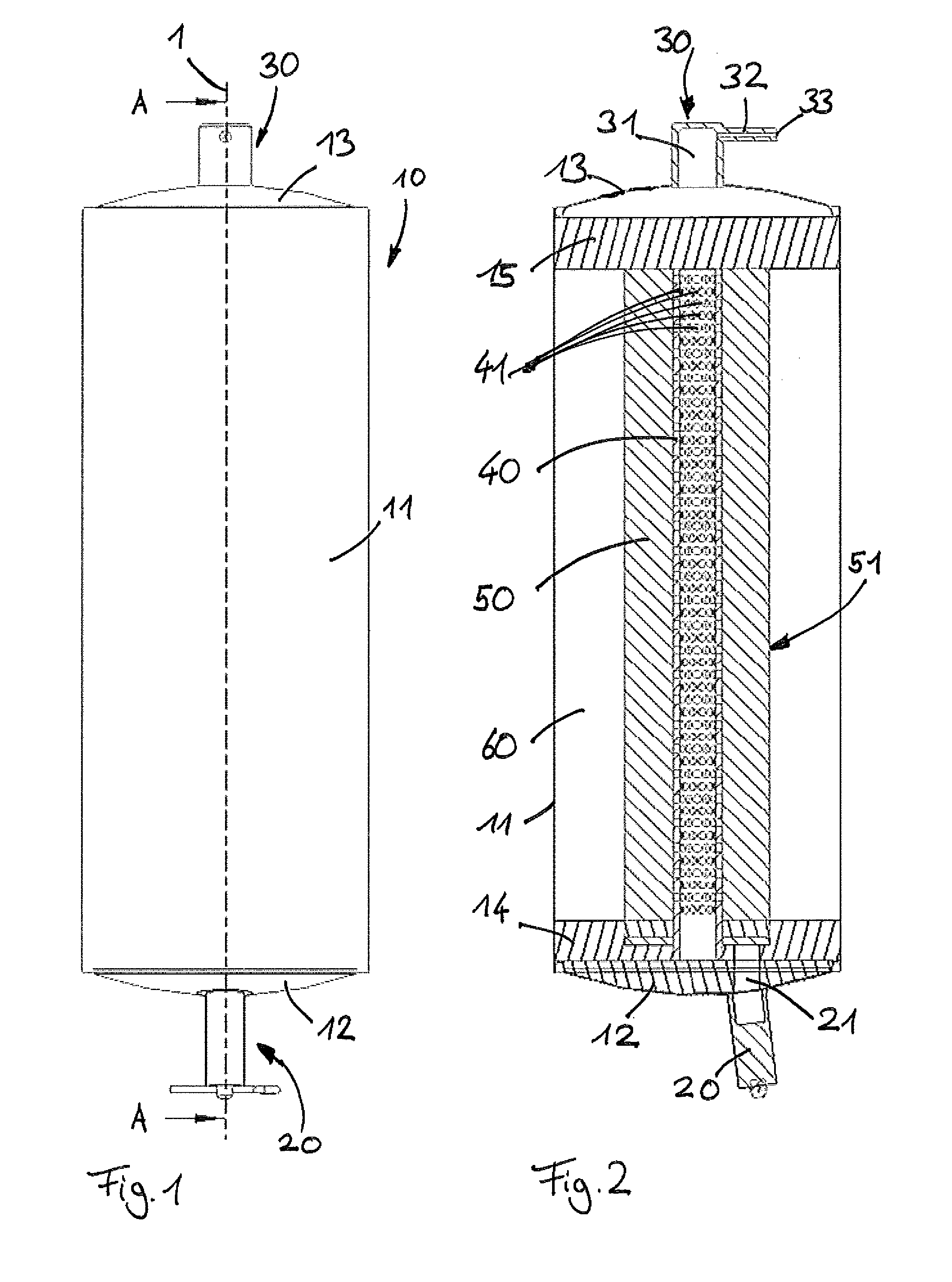
[0032]Referring first to FIG. 1, an oxygen generator according to the invention comprises a cylindrical housing 10 extending along a longitudinal axis 1.

[0033]The housing 10 comprises a cylindrical wall 11, a front end cover 12 and a back end cover 13.

[0034]A piezoelectrical starter unit is attached to the front end cover 12.

[0035]An outlet conduct 30 is attached to the back end cover 13. The outlet conduct 30 comprises an axial portion 31 and a connector tube 32 having an outlet opening 33 for connecting a tube or hose to the oxygen generator for directing the oxygen to an oxygen mask.

[0036]As can be seen in detail from FIG. 2, a hollow tube 40 extends along the longitudinal axis 1 inside the housing 10. The hollow tube 40 is arranged co-axis to the longitudinal axis 1. The hollow tube is perforated with a plurality of radial openings 41.

[0037]The hollow tube 40 is embedded in a solid oxygen source material 50 comprising sodium chlorate. Said solid oxygen source has a ring-shaped c...

second embodiment

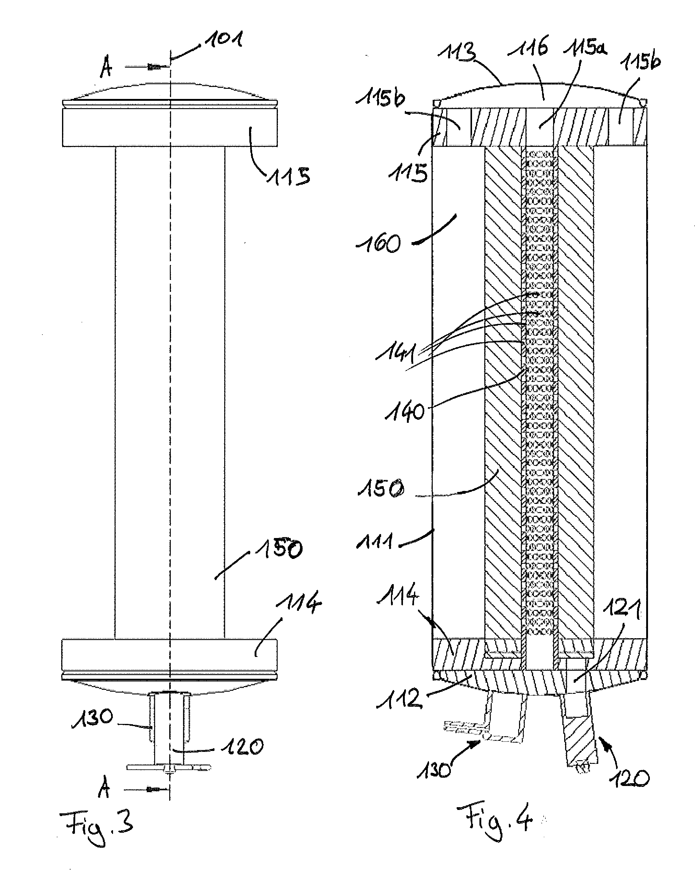
[0044]The back end cover 113 of the second embodiment is a closed cover with a slightly convex shape. It defines a flow chamber 116 which is in fluid communication with a central opening 115a in the ring-shaped element 115 and a plurality of eccentric openings 115b in said ring-shaped element 115. The openings 115a and b are oriented in an axial direction parallel to the longitudinal axial 101 of the oxygen generator. The central opening 115a is in fluid communication with the interior of the hollow tube 140. The eccentric openings 115b are in fluid communication with a hollow space 160 located between the solid oxygen source 150 and the cylindrical wall 111 of the housing.

[0045]Upon ignition and start of the chemical reaction by the starter unit 120 oxygen is produced close to the front end cover 112 in the solid oxygen source 150. The oxygen enters the interior of the hollow tube 140 through the perforations 141 and flows from the front end cover 112 to the back end cover 113. The...


PUM


Abstract

Embodiments of the invention relate to a chemical oxygen generator for an emergency oxygen device, comprising an outer housing defining an interior space and comprising an outlet opening, a solid oxygen source within said interior space containing a material which is able to produce oxygen in a chemical reaction. According to embodiments of the invention, a hollow tube within said interior space is embedded in said solid oxygen source.

Description

FIELD OF THE INVENTION[0001]Embodiment of the invention relate to a chemical oxygen generator for an emergency oxygen device, comprising an outer housing defining an interior space and comprising an outlet opening, a solid oxygen source within said interior space containing a material which is able to produce oxygen in a chemical reaction. A further aspect of the invention is an emergency oxygen device, comprising such an chemical oxygen generator.BACKGROUND[0002]Chemical oxygen generators of this type are used as an alternative to oxygen pressure tanks in emergency oxygen devices installed on board of civil aircraft mainly. These emergency oxygen devices serve to supply oxygen to passenger or cabin crew in case of an emergency situation like a decompression situation. In such a situation an oxygen flow is provided to an oxygen mask which can be worn by the passenger in order to allow him constant breathing and sufficient uptake of oxygen for his vital functions.[0003]It is known in...

Claims


Application Information

Patent Timeline
IPC IPC(8): A62B7/08A62B18/02A62B7/10
CPCA62B7/00A62B7/08A62B21/00A62B7/14
Inventor RITTNER, WOLFGANGMECKES, RUDIGER
Owner SAFRAN AEROTECHNICS
Learn More