System and method for lubricating gears in a wind turbine

a technology of wind turbines and gear lubrication, which is applied in the direction of manual lubrication, machines/engines, distribution equipment, etc., can solve the problems of frictional corrosion in this localized area without frequent and regular lubrication, and the engaged teeth between the driving pinion gear and the ring gear are difficult to access for greasing

Active Publication Date: 2013-08-01
GENERAL ELECTRIC CO
View PDF8 Cites 32 Cited by
  • Summary
  • Abstract
  • Description
  • Claims
  • Application Information

AI Technical Summary

Benefits of technology

[0009]In a particular embodiment, the grease distributor is variably positionable on the pinion gear such that the channel member is positionable in different tooth valleys of the pinion gear. In this embodiment, the distributor may have less channel members than there are valleys in the pinion gear such that the distributor delivers grease to only a defined sector of the pinion gear. For example, the distributor ...

Problems solved by technology

The engaged pitch drive gears in this localized area are subjected to relatively high loads induced in large part by the torsional forces acting on the blades.
Frictional corrosion can occur in this area without...

Method used


Image

  • System and method for lubricating gears in a wind turbine
  • System and method for lubricating gears in a wind turbine
  • System and method for lubricating gears in a wind turbine

Examples


Embodiment Construction

[0026]Reference now will be made in detail to embodiments of the invention, one or more examples of which are illustrated in the drawings. Each example is provided by way of explanation of the invention, not limitation of the invention. In fact, it will be apparent to those skilled in the art that various modifications and variations can be made in the present invention without departing from the scope or spirit of the invention. For instance, features illustrated or described as part of one embodiment can be used with another embodiment to yield a still further embodiment. Thus, it is intended that the present invention covers such modifications and variations as come within the scope of the appended claims and their equivalents.

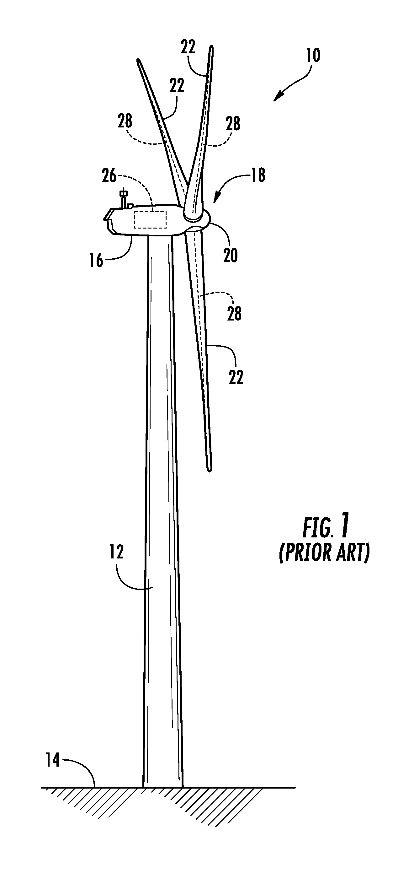
[0027]Referring now to the drawings, FIG. 1 illustrates a perspective view of one embodiment of a conventional wind turbine 10. As shown, the wind turbine 10 generally includes a tower 12 extending from a support surface 14, a nacelle 16 mounted on the towe...


PUM


Abstract

A system and method for lubricating gears in a wind turbine blade pitch drive are provided, wherein the pitch drive comprises a drive pinion gear with gear teeth that engage a pitch bearing gear coupled to a respective wind turbine blade. A grease distributor is configured to mount onto and rotate with the pinion gear, and is configured to deliver grease from an external grease supply to at least one valley defined between adjacent teeth of the pinion gear in a contact area of the pinion gear with the bearing gear without the distributor contacting inter-engaging teeth of the bearing gear.

Description

FIELD OF THE INVENTION[0001]The present subject matter relates generally to wind turbines and, more particularly, to a system lubricating gears in the wind turbine, especially turbine blade pitch gears.BACKGROUND OF THE INVENTION[0002]Generally, a wind turbine includes a tower, a nacelle mounted on the tower, and a rotor coupled to the nacelle. The rotor typically includes a rotatable hub and a plurality of rotor blades coupled to and extending outwardly from the hub. Each rotor blade may be spaced about the hub so as to facilitate rotating the rotor to enable kinetic energy to be transferred from the wind into usable mechanical energy, and subsequently, electrical energy.[0003]Proper lubrication of the various open gears in wind turbines has proven to be an important consideration in the operation and maintenance of the systems. This is especially true for the pitch control gears associated with each of the turbine blades. These gears operate in a relatively small defined positiona...

Claims


Application Information

Patent Timeline
IPC IPC(8): F16H57/04
CPCY02E10/722F03D11/0008F16H57/0464F16H57/0456F16H57/0431F03D80/70Y02E10/72
Inventor SEGOVIA, EUGENIO YEGRONIES, JACOB JOHANNESSANTIAGO, PEDRO LUIS BENITOGARRIDO, ALVARO JAIME CALLELOPEZ, MIGUEL BARTOLOME
Owner GENERAL ELECTRIC CO
Why Eureka
Try Eureka