
Resonant converter with auxiliary resonant components and holdup time control circuitry

a technology of auxiliary resonant components and holdup time control circuits, which is applied in the direction of electric variable regulation, process and machine control, instruments, etc., can solve the problems of difficult to achieve better performance (e.g., higher efficiency), undesirable side effects of the converter, and may be provided with solutions to meet the requirements. achieve the effect of high converter efficiency and not negatively affecting the high efficiency of the converter

Inactive Publication Date: 2013-08-01
BEL POWER SOLUTIONS INC
View PDF5 Cites 50 Cited by
  • Summary
  • Abstract
  • Description
  • Claims
  • Application Information

AI Technical Summary

Benefits of technology

The present invention relates to a resonant converter that can control certain parameters (e.g. resonant parameters) to minimize the time needed to startup and then return them to their initial value when the startup period is over to increase efficiency. The control mode for the converter remains in effect only during the startup period and doesn't negatively affect the high efficiency of the converter. The gain curve of the LLC converter suggests that increasing the size of the resonant capacitor, inductor, and power transformer can enhance the time needed to startup.

Problems solved by technology

However, achieving better performance (e.g., higher efficiency) is difficult because any combination of requirements for a holdup time, peak power, and wide input range regulation must be concurrently satisfied.
In other words, any solution which may be provided to meet the requirements for holdup time, peak power, and / or wide regulation range, will generally have undesirable side effects with respect to the efficiency of the converter.

Method used


Image

  • Resonant converter with auxiliary resonant components and holdup time control circuitry
  • Resonant converter with auxiliary resonant components and holdup time control circuitry
  • Resonant converter with auxiliary resonant components and holdup time control circuitry

Examples


Embodiment Construction

[0024]Throughout the specification and claims, the following terms take at least the meanings explicitly associated herein, unless the context dictates otherwise. The meanings identified below do not necessarily limit the terms, but merely provide illustrative examples for the terms. The meaning of “a,”“an,” and “the” may include plural references, and the meaning of “in” may include “in” and “on.” The phrase “in one embodiment,” as used herein does not necessarily refer to the same embodiment, although it may.

[0025]The term “coupled” means at least either a direct electrical connection between the connected items or an indirect connection through one or more passive or active intermediary devices. The term “circuit” means at least either a single component or a multiplicity of components, either active and / or passive, that are coupled together to provide a desired function. The term “signal” as used herein may include any meanings as may be understood by those of ordinary skill in ...


PUM


Abstract

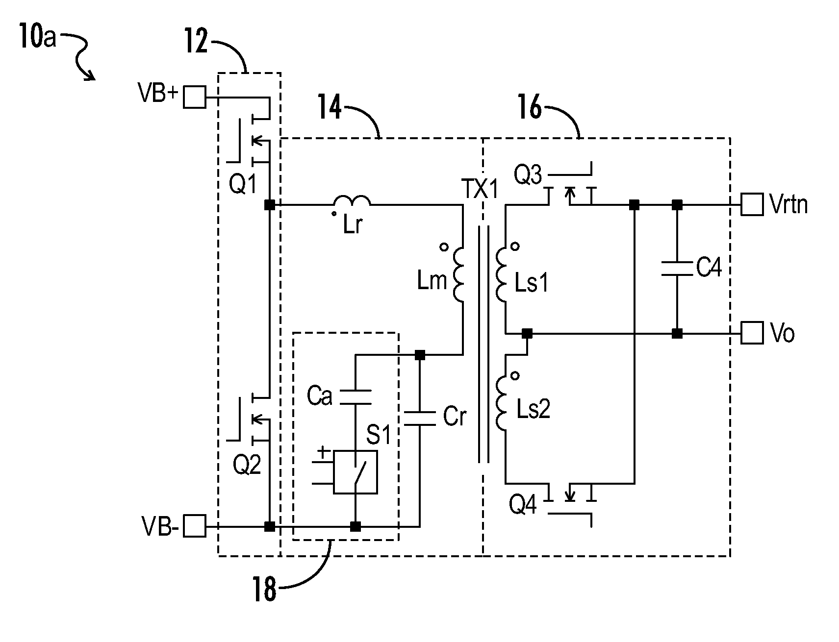
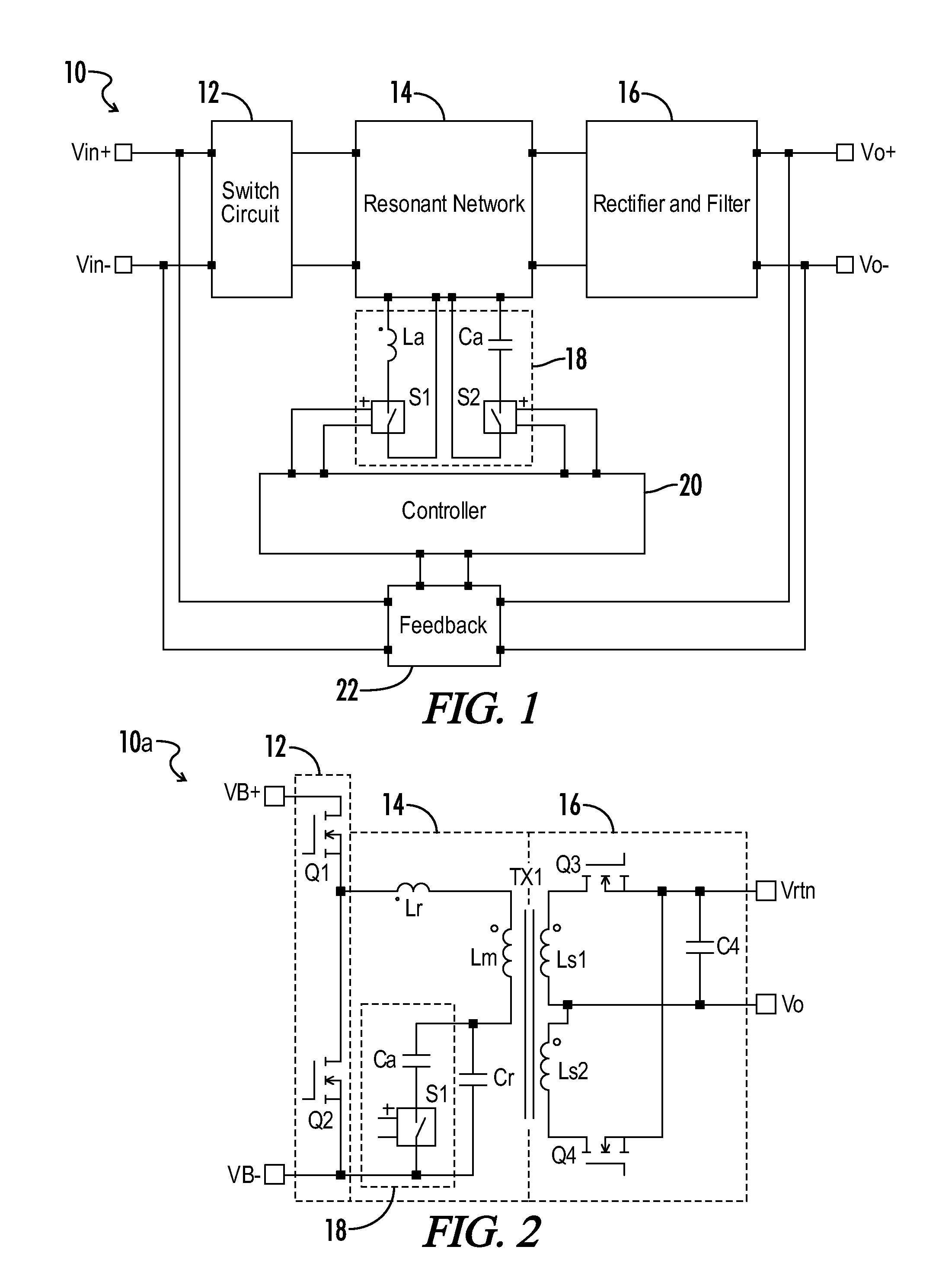
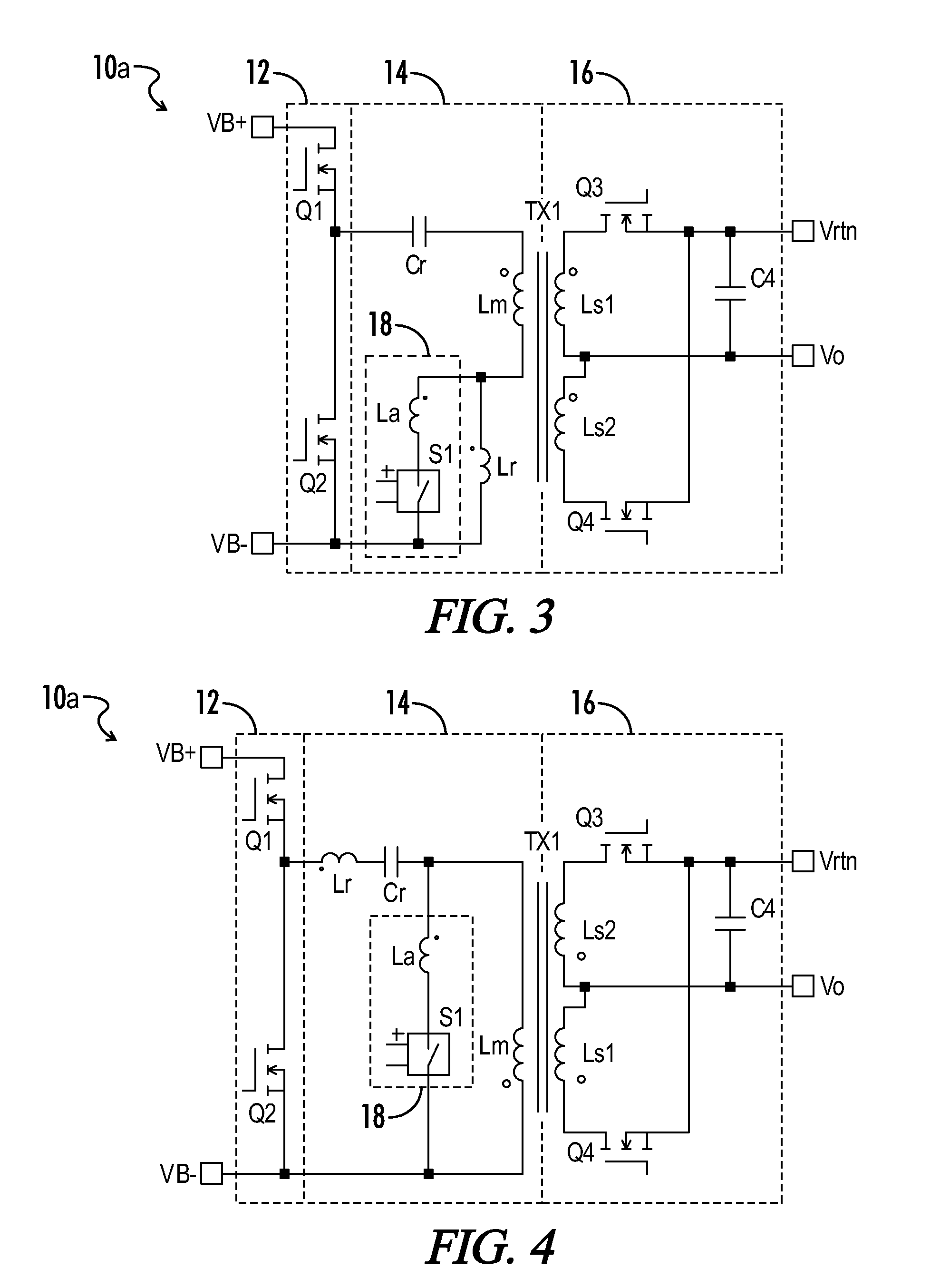
A resonant power converter is provided with auxiliary circuit branches and control circuitry for switchably coupling the auxiliary branches to resonant circuit components during holdup times. Auxiliary branches are coupled in parallel with any one or more of a resonant inductor, a resonant capacitor, and a magnetizing inductive winding via respective switches. When a holdup time condition is detected in accordance with, for example, a drop in the mains line voltage, the switches are controlled to adjust the corresponding inductance or capacitance for the duration of the holdup time condition or otherwise for a predetermined duration. The power converter in normal operation is configured for high efficiency and in a holdup time operation is configured to produce sufficient holdup time.

Description

CROSS-REFERENCES TO RELATED APPLICATIONS[0001]This application claims benefit of the following patent application which is hereby incorporated by reference: U.S. Provisional Patent Application No. 61 / 586,541, filed Jan. 13, 2012.[0002]A portion of the disclosure of this patent document contains material that is subject to copyright protection. The copyright owner has no objection to the reproduction of the patent document or the patent disclosure, as it appears in the U.S. Patent and Trademark Office patent file or records, but otherwise reserves all copyright rights whatsoever.BACKGROUND OF THE INVENTION[0003]The present invention relates generally to resonant power converters. More particularly, the present invention relates to gain enhancement techniques in resonant power converters through the use of auxiliary components and associated control circuitry.[0004]Resonant converters (e.g., LLC converters) have become a popular topology in power conversion applications and can genera...

Claims


Application Information

Patent Timeline
Patent Type & Authority Applications(United States)
IPC IPC(8): H02M3/335
CPCH02M3/33507H02M3/33569Y02B70/1491H02M2001/0058Y02B70/1433Y02B70/10Y02P80/10H02M1/0058H02M3/33573H02M3/33571H02M3/01H02M1/32H02M1/325
Inventor HU, GORDON ZONGBO
Owner BEL POWER SOLUTIONS INC
Learn More