
Integrated solvent deasphalting and steam pyrolysis process for direct processing of a crude oil

a technology of integrated solvent and crude oil, which is applied in the direction of working up pitch/asphalt/bitumen by selective extraction, thermal non-catalytic cracking, and treatment with plural serial stages only, etc., and can solve the problems of coke formation in conventional heavy hydrocarbon pyrolysis operations, cost and energy-intensive process steps, and limited availability of feedstocks

Inactive Publication Date: 2013-08-01
SAUDI ARABIAN OIL CO
View PDF0 Cites 14 Cited by
  • Summary
  • Abstract
  • Description
  • Claims
  • Application Information

AI Technical Summary

Benefits of technology

The patent describes a system and process that enables the direct processing of crude oil to produce petrochemicals like olefins and aromatics. The process involves combining a solvent deasphalting zone with a steam pyrolysis zone, which allows for the separation and recovery of valuable oil components. The use of crude oil that has undergone some pre-treatment, such as water-oil separation or desalting, is also included. The technical effects of this process are improved efficiency and flexibility in the production of petrochemicals from crude oil, reducing the need for expensive and time-consuming pre-treatment steps.

Problems solved by technology

The availability of these feedstocks is usually limited and requires costly and energy-intensive process steps in a crude oil refinery.
A major drawback in conventional heavy hydrocarbon pyrolysis operations is coke formation.
In a comparative example without the addition of molten salt, the steam cracking reactor became clogged and inoperable after just 5 hours because of the formation of coke in the reactor.
While the steam pyrolysis process is well developed and suitable for its intended purposes, the choice of feedstocks has been very limited.

Method used


Image

  • Integrated solvent deasphalting and steam pyrolysis process for direct processing of a crude oil
  • Integrated solvent deasphalting and steam pyrolysis process for direct processing of a crude oil
  • Integrated solvent deasphalting and steam pyrolysis process for direct processing of a crude oil

Examples


Embodiment Construction

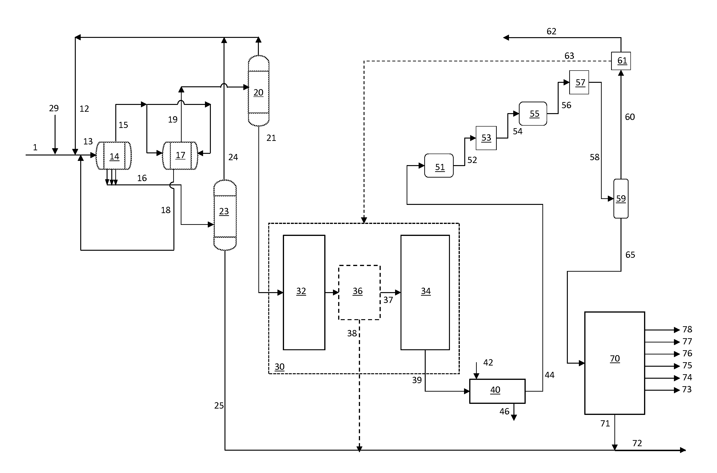
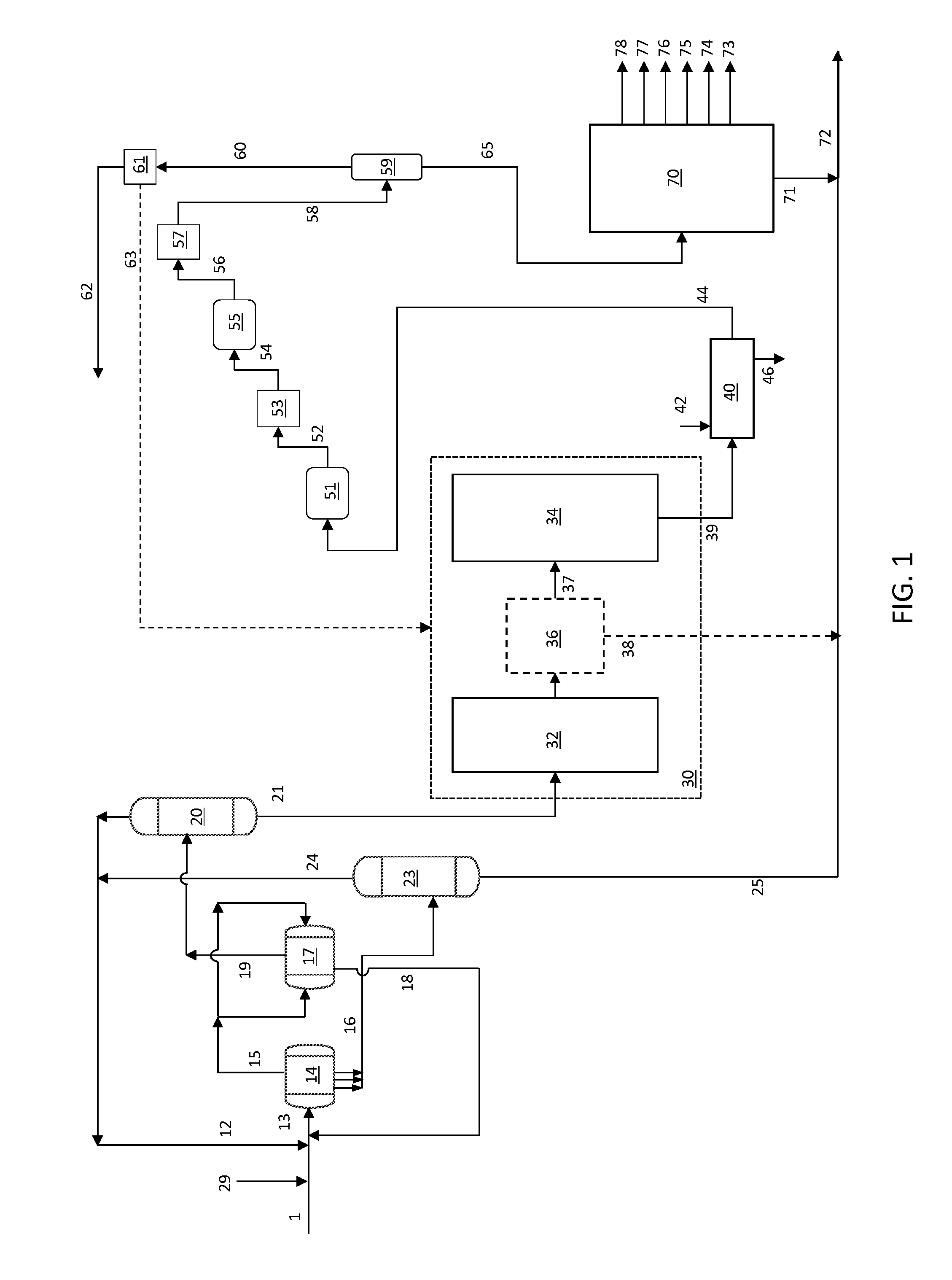
[0021]A flow diagram including an integrated solvent deasphalting and steam pyrolysis process and system is shown in FIG. 1. The integrated system includes a solvent deasphalting zone, a steam pyrolysis zone 30 and a product separation zone.

[0022]Solvent deasphalting zone generally includes a primary settler 14, a secondary settler 17, a deasphalted / demetalized oil (DA / DMO) separation zone 20, and a separator zone 23.

[0023]Primary settler 14 includes an inlet for receiving a combined stream 13 including a feed stream 1 and a solvent, which can be fresh solvent 29, recycle solvent 12, recycle solvent 24, or a combination comprising one or more of these solvent sources. Primary settler 14 also includes an outlet for discharging a primary DA / DMO phase 15 and several pipe outlets for discharging a primary asphalt phase 16. Secondary settler 17 includes two tee-type distributors located at both ends for receiving the primary DA / DMO phase 15, an outlet for discharging a secondary DA / DMO p...


PUM

PropertyMeasurementUnit
liquidaaaaaaaaaa
physicalaaaaaaaaaa
weightaaaaaaaaaa

Abstract

A process is provided that is directed to a steam pyrolysis zone integrated with a solvent deasphalting zone to permit direct processing of crude oil feedstocks to produce petrochemicals including olefins and aromatics. The integrated solvent deasphalting and steam pyrolysis process for the direct processing of a crude oil to produce olefinic and aromatic petrochemicals comprises charging the crude oil to a solvent deasphalting zone with an effective amount of solvent to produce a deasphalted and demetalized oil stream and a bottom asphalt phase; thermally cracking the deasphalted and demetalized oil stream in the presence of steam to produce a mixed product stream; separating the mixed product stream; recovering olefins and aromatics from the separated mixed product stream; and recovering pyrolysis fuel oil from the separated mixed product stream.

Description

RELATED APPLICATIONS[0001]This application claims the benefit of U.S. Provisional Patent Application No. 61 / 591,783 filed Jan. 27, 2012, the disclosure of which is hereby incorporated by reference in its entirety.BACKGROUND OF THE INVENTION[0002]1. Field of the Invention[0003]The present invention relates to an integrated solvent deasphalting and steam pyrolysis process for direct processing of a crude oil to produce petrochemicals such as olefins and aromatics.[0004]2. Description of Related Art[0005]The lower olefins (i.e., ethylene, propylene, butylene and butadiene) and aromatics (i.e., benzene, toluene and xylene) are basic intermediates which are widely used in the petrochemical and chemical industries. Thermal cracking, or steam pyrolysis, is a major type of process for forming these materials, typically in the presence of steam, and in the absence of oxygen. Feedstocks for steam pyrolysis can include petroleum gases and distillates such as naphtha, kerosene and gas oil. The ...

Claims


Application Information

Patent Timeline
Patent Type & Authority Applications(United States)
IPC IPC(8): C10G55/04
CPCC10G55/04C10G47/22C10G47/34C10G21/003C10G67/049C10G9/16C10G67/04
Inventor BOURANE, ABDENNOURSHAFI, RAHEELSAYED, ESSAMABBA, IBRAHIM A.AKHRAS, ABDUL RAHMAN ZAFER
Owner SAUDI ARABIAN OIL CO
Learn More