Vessel propulsion apparatus

a propulsion apparatus and vessel technology, applied in the direction of marine propulsion, propellant elements, vessel construction, etc., can solve the problems of not being able to provide catalyst in all exhaust systems, and the degradation of exhaust sensors

Active Publication Date: 2013-08-08
YAMAHA MOTOR CO LTD
View PDF3 Cites 8 Cited by
  • Summary
  • Abstract
  • Description
  • Claims
  • Application Information

AI Technical Summary

Benefits of technology

[0017]With this arrangement of the present preferred embodiment of the present invention, the non-catalytic porous member is disposed in the upward guiding portion that extends upward toward the downstream side and the exhaust sensor is disposed in the downward guiding portion extending downward toward the downstream side. The downward guiding member is disposed at the downstream side relative to the upward guiding portion. Thus, at least one top portion (for exampl...

Problems solved by technology

Specifically, when a temperature of an exhaust pipe is high, corrosion of metal due to water, such as seawater, occurs, and thus in a vessel propulsion apparatus, an exhaust pipe is cooled by cooling water of lower temperature than in an internal circulation type cooling device included in an aut...

Method used


Image

  • Vessel propulsion apparatus
  • Vessel propulsion apparatus
  • Vessel propulsion apparatus

Examples


Embodiment Construction

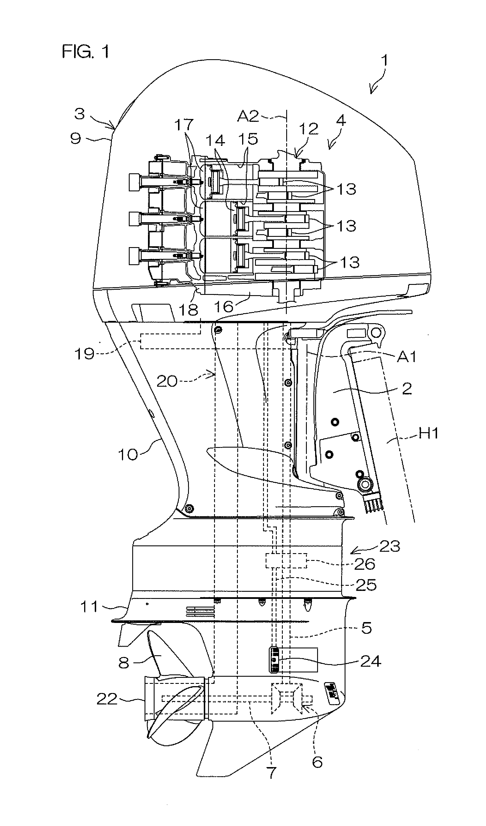
[0026]FIG. 1 is a side view of a vessel propulsion apparatus 1 according to a preferred embodiment of the present invention. To facilitate understanding, FIG. 1 shows an interior of an engine cover 9 in a see-through manner.

[0027]The vessel propulsion apparatus 1 includes a bracket 2 attachable to a rear portion of a hull H1 and an outboard motor 3 supported by the bracket 2 in a manner enabling rotation around a steering axis Al extending in a vertical direction.

[0028]The outboard motor 3 includes an engine 4, a driveshaft 5, a forward-reverse switching mechanism 6, and a propeller shaft 7. The outboard motor 3 further includes the engine cover 9 housing the engine 4, an upper casing 10 disposed below the engine cover 9, and a lower casing 11 disposed below the upper casing 10. The driveshaft 5 extends downward from the engine 4, and a lower end portion of the driveshaft 5 is coupled to a front end portion of the propeller shaft 7 via the forward-reverse switching mechanism 6. The ...


PUM


Abstract

A vessel propulsion apparatus includes an exhaust passage guiding exhaust generated at an engine, a water jacket cooling at least a portion of the exhaust passage, a cooling device supplying water outside the vessel propulsion apparatus to the water jacket, an exhaust sensor detecting a concentration of a component in the exhaust in the exhaust passage, and a non-catalytic porous member disposed in the exhaust passage at an upstream side relative to the exhaust sensor. The non-catalytic porous member is a porous member that does not hold a catalyst.

Description

BACKGROUND OF THE INVENTION[0001]1. Field of the Invention[0002]The present invention relates to a vessel propulsion apparatus.[0003]2. Description of the Related Art[0004]U.S. Pat. No. 7,867,048 B2 discloses an outboard motor with which an oxygen concentration inside an exhaust pipe is detected by an oxygen concentration sensor. U.S. Pat. No. 7,698,889 B2 discloses an exhaust system for a marine engine in which an oxygen concentration inside an exhaust pipe is detected by an oxygen concentration sensor. A catalyst that purifies the exhaust inside the exhaust pipe is disposed at an upstream side relative to the oxygen concentration sensor. A honeycomb member that captures water flowing in reverse inside the exhaust pipe toward a combustion chamber is disposed at a downstream side relative to the oxygen concentration sensor.SUMMARY OF THE INVENTION[0005]The inventor of preferred embodiments of the present invention described and claimed in the present application conducted an extensi...

Claims


Application Information

Patent Timeline
IPC IPC(8): B63H21/32
CPCB63H20/24
Inventor SUZUKI, ATSUSHI
Owner YAMAHA MOTOR CO LTD
Why Eureka
Try Eureka