Photovoltaic module with integrated solar cell diodes

Inactive Publication Date: 2013-08-15
INNOTECH SOLAR
View PDF2 Cites 25 Cited by
  • Summary
  • Abstract
  • Description
  • Claims
  • Application Information

AI Technical Summary

Benefits of technology

[0016]As a large surface area is disposed substantially flush with the front and/or rear surface of the module, excess heat can be dissipated by radiation directly from the diode surface, rather than being conducted to an external heat sink or radiator. This may reduce or eliminate the requirement for

Problems solved by technology

This can permanently damage the cell and the module.
A typical thin film diode cannot withstand typical currents in a modern high efficiency 15 cm (6 inch) silicone crystalline cell, such as about 8.5 A. Furthermore, a thin or narrow diode also generates heat when employed in a modern cell or module with higher currents.
As the surface area of a thin and narrow structure tends to be too small to radiate away the heat to the surrounding environment, such diodes often require good thermal coupling to a heat sink with a sufficiently large surface area to dissipate the excess heat by radiation.
Accumulated heat could cause overheating and permanent damage on the solar cell and the module, and adding good thermal conductors which do not conduct electricity to numerous small diodes quickly adds to the complexity and cost of a solar module producing voltages and currents for present applications.
Further, integrating the diodes in a solar cell such as in the above references tends to be complicated, and increases the risk of breakage and yield losses.
Today, common practice is to install one bypass diode in parallel over 20 cells, as this is found to be a r

Method used


Image

  • Photovoltaic module with integrated solar cell diodes
  • Photovoltaic module with integrated solar cell diodes
  • Photovoltaic module with integrated solar cell diodes

Examples


Example

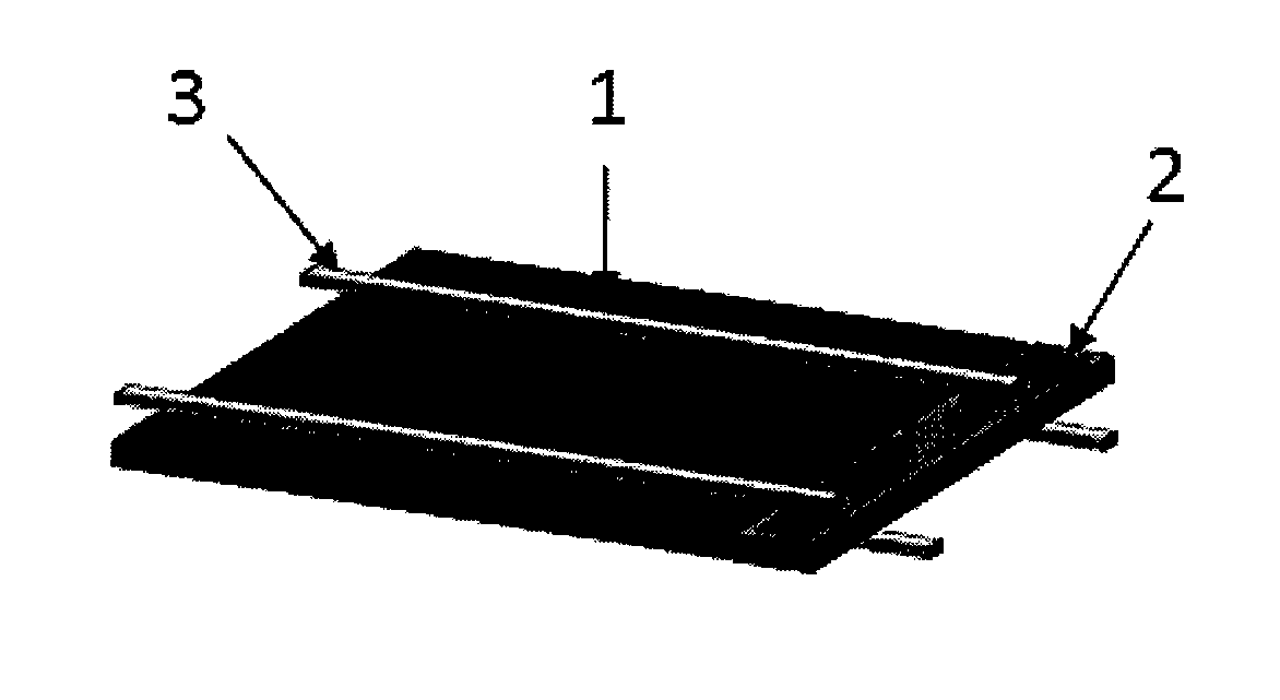
[0043]FIG. 1 shows a single solar cell protected by a bypass diode 2. The diode is electrically connected in parallel to one or more production cells 1 by electrical connectors 3, and provides a path for the reverse currents generated when one or more of the production cells 1 are shaded as discussed in the introduction.

[0044]The wording connector(s) 3 or ribbon(s) are used interchangeably throughout the description to describe conductors interconnecting for example production cells and bypass diodes.

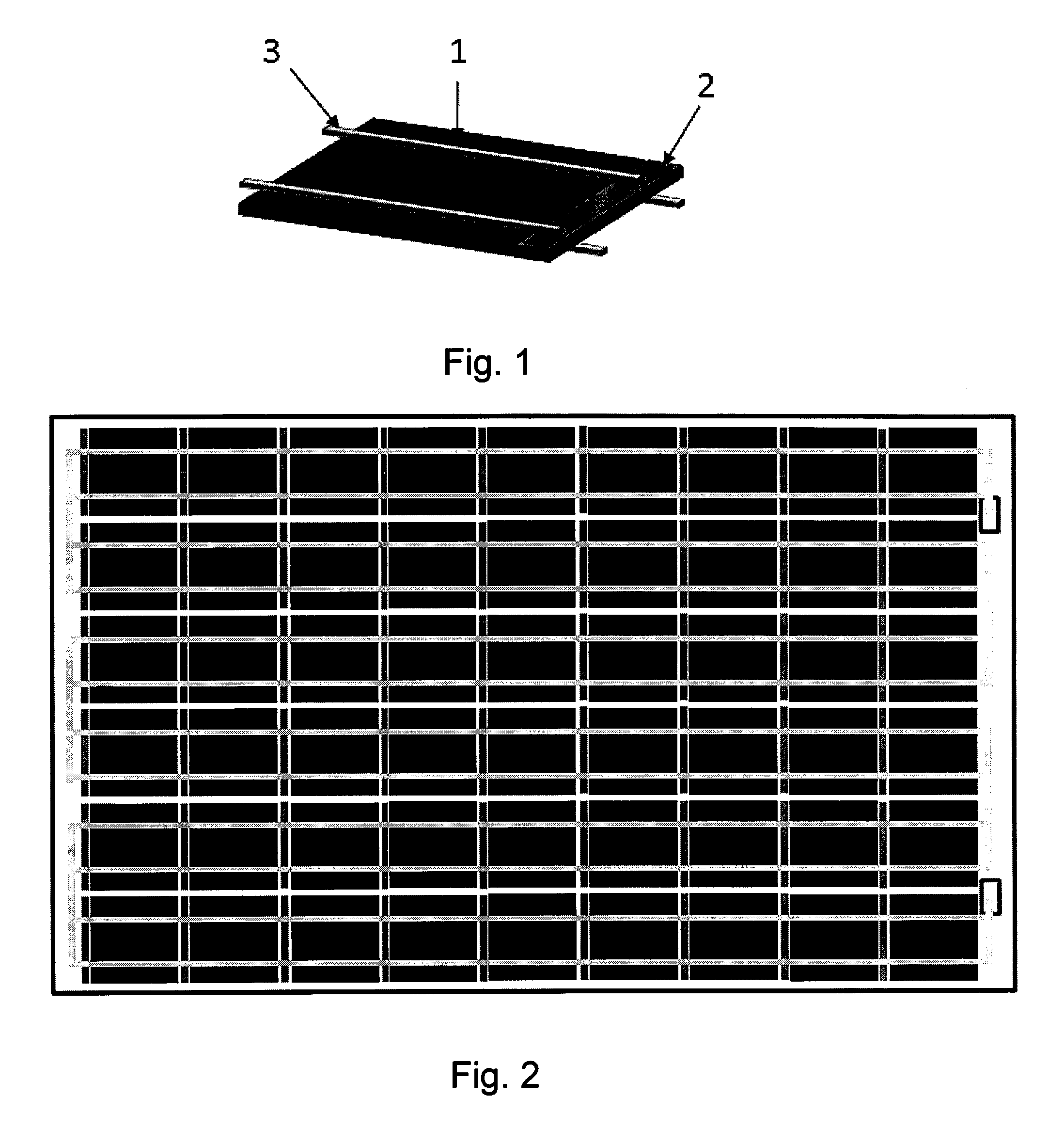
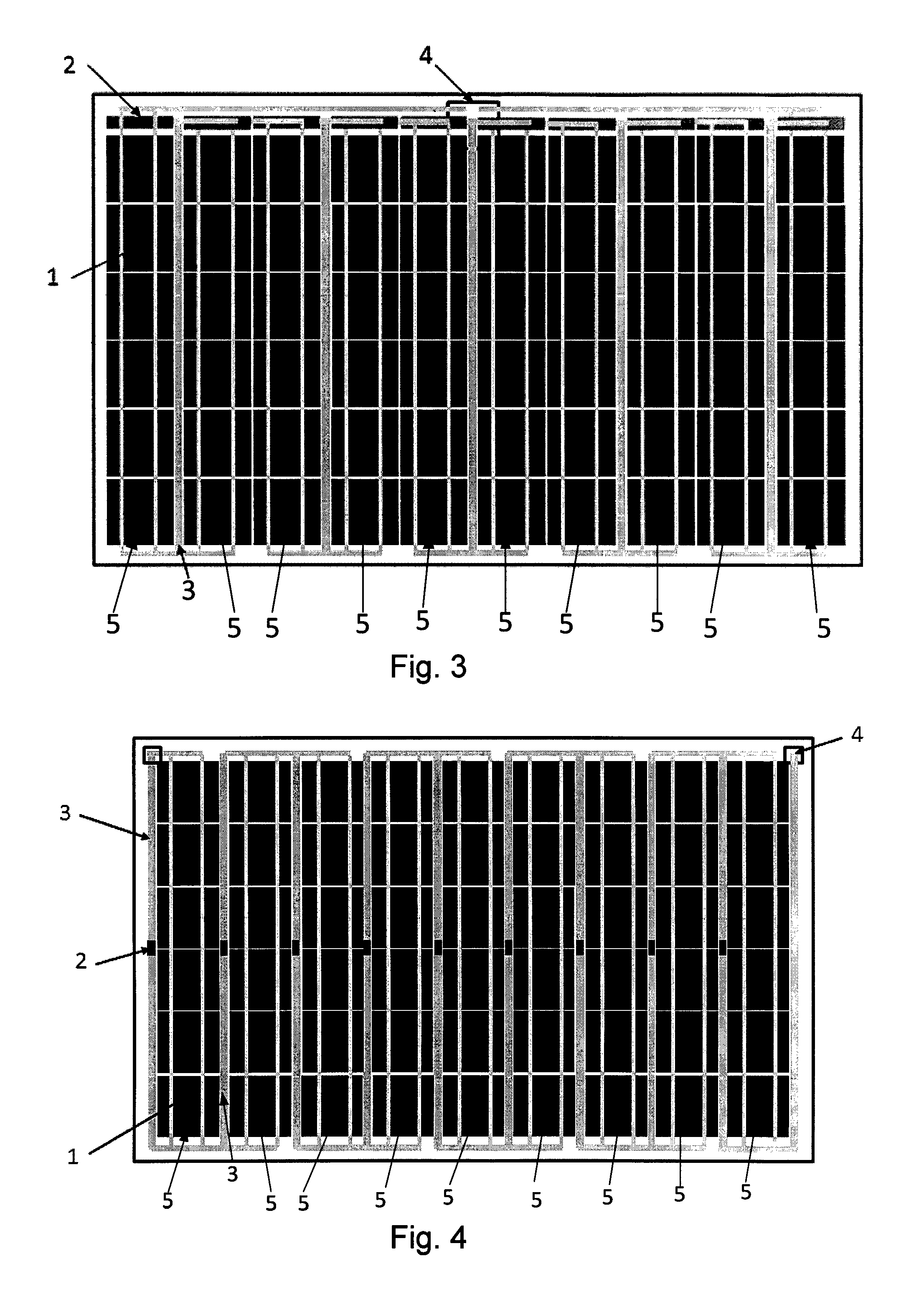
[0045]A solar module comprises a plurality of single solar cells. The maximum heating in a module occurs when one cell in a string 5 is shaded or partially shaded so that it 5 does not produce enough light generated current in forward bias to match the current generated by all the other unshaded cells in the same string 5 and hence goes into reverse bias as the current is forced through the shaded cell by the potential created by all the unshaded cells in the same string 5. Or the maxim...


PUM


Abstract

A solar module having a plurality of series connected pn junction production solar cells, where at least one bypass diode (2) is provided with a surface area adapted to dissipate heat generated from one or more of the series connected production cells. A substantial part of the surface area is disposed substantially flush with the front and/or rear face of a production cell. The bypass diode (2) is electrically connected in parallel and with opposite polarity to at least one production cell (1) by electrical conductors (3).

Description

TECHNICAL FIELD[0001]The present invention relates to an apparatus and method for protecting solar cells from the effects of shading, in particular reverse bias, reverse current and hotspots caused by shading. In particular it is provided a solar module comprising a plurality of series connected pn junction production solar cells, where at least one bypass diode is provided, it is also provided a method for producing the same.BACKGROUND ART[0002]Within a solar module typically a plurality of solar cells are connected in series to provide technically useful voltages and currents. In case of partial shadowing of the solar module, the shadowed solar cells will generate less or even no current and will not conduct the current in the normal forward bias mode. (The current in a series connected string of cells must be the same in all cells.) The voltage of the illuminated cells will build up a reverse bias voltage on the shadowed cells until a steady state current is reached. The reverse ...

Claims


Application Information

Patent Timeline
IPC IPC(8): H01L31/05H10K39/10H10K59/90
CPCH01L31/0504H01L31/044Y02E10/50H01L31/052H02S40/42Y02E10/547
Inventor LOMMASSON, TIMOTHY CHARLESHOFMULLER, ECKEHARD
Owner INNOTECH SOLAR
Why Eureka
Try Eureka