Mining vehicle and method for its energy supply

a technology for mining vehicles and energy supply, which is applied in the direction of electric propulsion mounting, battery/cell propulsion, transportation and packaging, etc. it can solve the problems of mine fire safety, combustion engine requires a lot of space on the carriage of the vehicle, and combustion engine also has adverse effects on the fire safety of the mine, so as to reduce the load of the supply network, and the effect of good adjustability

Active Publication Date: 2013-08-15
SANDVIK MINING & CONSTR OY
View PDF3 Cites 21 Cited by
  • Summary
  • Abstract
  • Description
  • Claims
  • Application Information

AI Technical Summary

Benefits of technology

[0010]The mining vehicle obtains its energy supply mainly from the electrical network of the mine. The mining vehicle further has a rectifier, DC intermediate circuit, and inverter, which means that the mining vehicle has an alternating current electric motor. Further, at least one auxiliary energy source is connected to the DC intermediate circuit. A DC / DC converter is connected between the DC intermediate circuit and auxiliary energy source to adapt the voltage levels and charging / discharging current of the DC intermediate circuit and auxiliary energy source. This means that disparate auxiliary energy sources may be arranged to the DC intermediate circuit of the device. The power or charging capacity of the auxiliary energy sources may vary or they may be chemically different or their charging voltages may differ from each other, or new and old auxiliary energy sources maybe be used. In spite of the differences in the auxiliary energy sources, arranging them to the DC intermediate circuit is thus easy and simple thanks to the DC / DC converter. Further, thanks to the DC / DC converter it is possible to use several auxiliary energy sources in parallel, if required.
[0012]The idea of an embodiment is that the auxiliary energy source is connected to supply energy through the DC intermediate circuit to the electric motor of the mining vehicle when the energy requirement of the mining vehicle exceeds a certain limit. At the same time, energy is also supplied to the mining vehicle from the electrical network of the mine, which means that the auxiliary energy source acts as a supplier of additional energy. The electrical network of the mine is the primary energy source of the mining vehicle through the direct current circuit, that is, the DC intermediate circuit. Alternating current electric motors are energy efficient and their adjustability is good. Further, thanks to the rectifier, DC intermediate circuit and inverter, the system loads the electrical network almost solely with effective output, which reduces the load of the supply network in comparison with a situation where this arrangement does not exist. A three-phase motor connected to the DC intermediate circuit through the inverter is insensitive to the phase sequence of the supply network, whereby separate phase sequence control or change thereof is not needed. Further, the effect of the frequency of the supply network or the variation thereof on the electric motor of the mining vehicle can be eliminated. Problems caused to the electric system of the mining vehicle by over- or undervoltages of the electrical network of the mine can also be reduced when using the present solution. The power from the motor of the mining vehicle can be evened out by an auxiliary energy source connected to the intermediate circuit. Thus, in the presented solution, the auxiliary energy source evens out the load variations caused by the mining vehicle to the electrical network. This way, in a peak load situation, the current taken from the network can be kept lower than before, whereby the effective load of the mining vehicle decreases. The supply cable of the mining vehicle then need not be dimensioned for the peak power of the mining vehicle. All in all, the peak power and the size of idle power of the electrical network of the mine can thus be reduced.

Problems solved by technology

However, exhaust gases and noise from a combustion engine cause problems in mines.
In addition, a combustion engine requires a lot of space on the carriage of the vehicle, and necessitates regular maintenance.
A combustion engine also has adverse effects on the fire safety of the mine, since it has hot surfaces and it also is necessary to store and handle flammable fuel in the vehicle and mine.
A problem with such a mining vehicle that is fully dependent on batteries is the additional weight caused by the transported batteries.
In addition, the capacity of the batteries is quite limited, and the batteries of the mining vehicle need to be charged relatively often.

Method used


Image

  • Mining vehicle and method for its energy supply
  • Mining vehicle and method for its energy supply

Examples


Embodiment Construction

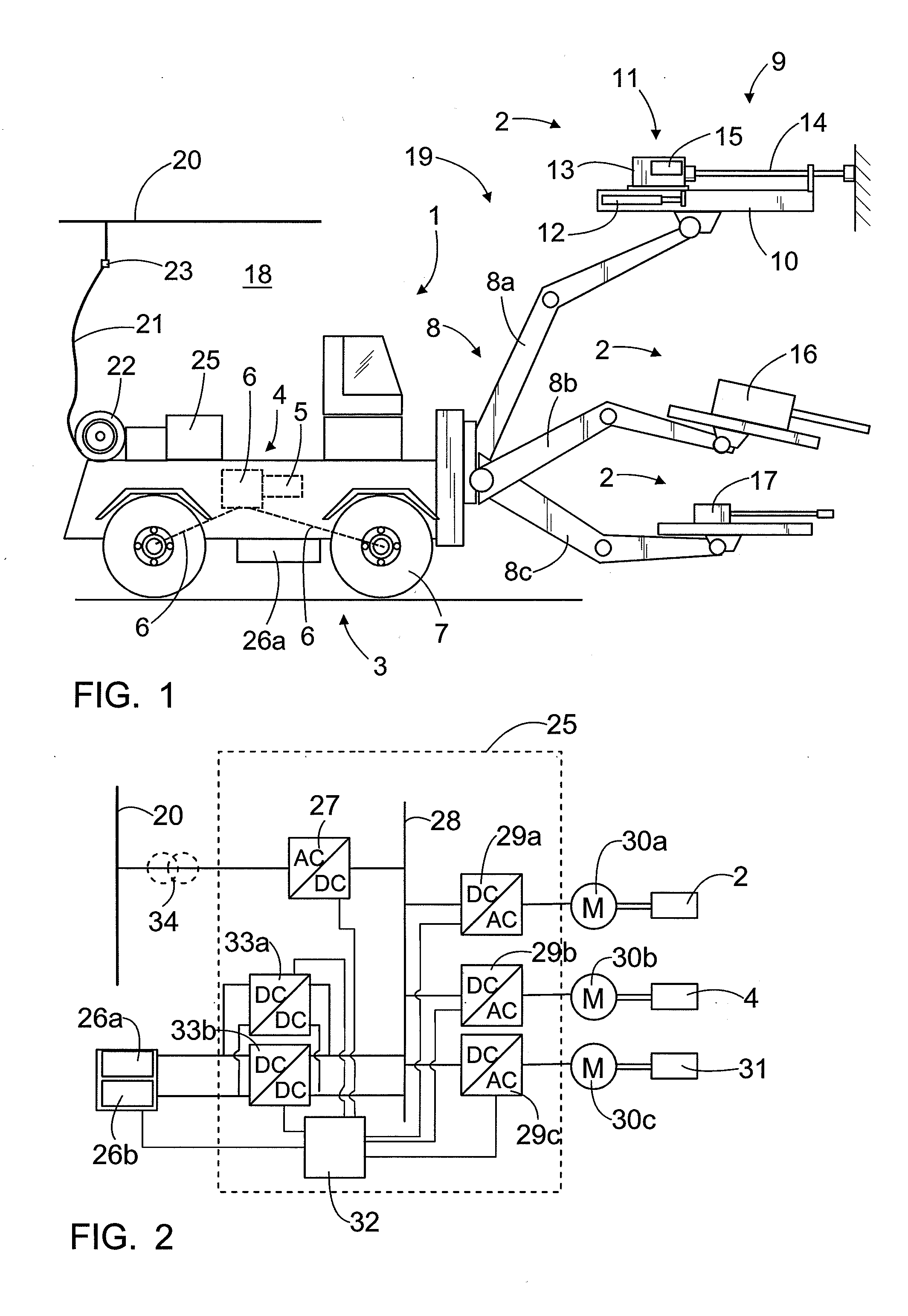
[0018]FIG. 1 shows a rock drilling rig that is one example of a mining vehicle 1 equipped with one or more mining work devices 2. The rock drilling rig comprises a carriage 3 that may be moved by means of drive equipment 4. The drive equipment 4 comprises one or more drive motors 5 and one or more power transmission means 6 for transmitting drive power to one or more wheels 7. The drive power transmission may comprise a mechanical gear system and mechanical power transmission members or, alternatively, the drive power transmission may be hydraulic or electric. There may be one or more booms 8 arranged on the carriage 3, and the boom may be equipped with a mining work device 2. In the embodiment shown in FIG. 1, the first boom 8a is a drilling boom, at the outermost end of which there is a rock drilling unit 9 comprising a feed beam 10, along which a rock drilling machine 11 may be moved by means of a feed device 12. The rock drilling machine 11 may comprise a percussion device 13 fo...


PUM


Abstract

The invention relates to a mining vehicle and method for its energy supply. The mining vehicle has a rectifier, DC intermediate circuit, and inverter, through which an alternating current motor is supplied. At least one auxiliary energy source is connected to the DC intermediate circuit. A DC / DC converter is connected between the DC intermediate circuit and the auxiliary energy source for adapting the voltage level of the auxiliary energy source and for connecting the auxiliary energy source to supply energy to the DC intermediate circuit.

Description

BACKGROUND OF THE INVENTION[0001]The invention relates to a mining vehicle with a carriage, drive equipment for moving the carriage, at least one mining work device which is one of the following: a rock drilling machine, bolting machine, shotcreting device, scaling device, injection device, blasthole charger, measuring device; alternating current electric motor, connection for supplying it from the electrical network of the mine, DC intermediate circuit to which electricity is supplied from the electrical network of the mine with a rectifier, inverter for supplying the electric energy of the DC intermediate circuit to the alternating current electric motor, and an auxiliary energy source connected to the DC intermediate circuit.[0002]The invention further relates to a method for the energy supply of a mining vehicle with a carriage, drive equipment for moving the carriage, at least one mining work device which is one of the following: a rock drilling machine, bolting machine, shotcr...

Claims


Application Information

Patent Timeline
Patent Type & Authority Applications(United States)
IPC IPC(8): B60L9/18B60L11/18
CPCB60K1/00Y02T10/7088B60L11/1801B60L11/1811B60L2200/40B60L2210/10B60Y2200/412B60Y2200/49E21B7/025Y02T10/7005Y02T10/7216Y02T90/127Y02T90/14B60L9/18B60L11/18B60L9/12Y02T10/7072B60L1/003B60L9/24H02J7/34Y02T10/92B60L50/53B60L53/20E21F17/06Y02T10/72Y02T10/70B60L9/16Y02T90/12
Inventor KOUVO, MIKKOOSARA, JUKKAPIIPPONEN, JUHA
Owner SANDVIK MINING & CONSTR OY
Why Eureka
Try Eureka