Sold photonic band gap fiber, fiber module using sold photonic band gap fiber, fiber amplifier, and fiber laser

a technology of sold photonic band gap, which is applied in the field of optical fiber, can solve the problems of both optical damage and non-linear optical effects, and the effect of reducing the effective core cross-sectional area, and reducing the difference between the bending loss of the fundamental mode (fm)

Active Publication Date: 2013-08-15
THE FUJIKURA CABLE WORKS LTD +1
View PDF4 Cites 13 Cited by
  • Summary
  • Abstract
  • Description
  • Claims
  • Application Information

AI Technical Summary

Benefits of technology

[0174]For example, even when the structures shown in FIGS. 9 and 10 are used, the effects of the invention can be exhibited as long as the structures are appropriately designed.
[0175]However, from the viewpoint of easy manufacturing, the high refractive index scatterers are desirably periodic.
[0176]Generally, the solid photonic band gap fiber is frequently manufactured using a stack-and-draw method, however, when the stack-and-draw method is considered, particularly, the high refractive index scatterers are most appropriately disposed periodically in a triangular grid shape.
[0177]FIG. 11 shows the dependency of bending loss on the number of layers of the high refractive index scatterers in a state in which a plurality of layers of the same high refractive index scatterers are periodically disposed in a triangular grid shape.
[0178]The bending loss of the fundamental mode (FM) is nearly independent of the number of layers.
[0179]On the other hand, regarding the bending loss of the high-order mode (HOM), when the number of layers of the high refractive index scatterers is three, the difference from the bending loss of the fundamental mode (FM) decreases.

Problems solved by technology

With regard to optical power, characteristics of an optical fiber to which attention should be paid are generally known to be optical damage and non-linear optical effects.
Both optical damage and non-linear optical effects are phenomena occurring when the power density (the optical power per unit light guide cross-sectional area) of light is high.
However, in that method, since the cutoff wavelength increases as the effective core cross-sectional area enlarges, there is a problem in that a tradeoff exists between single mode propagation necessary to maintain the beam qualities and enlargement of the effective core cross-sectional area.
132-139 (2004), in a case that a fiber is used in a bent state, there is a problem in that the effective core cross-sectional area significantly decreases, (regarding the behaviors of the effective core cross-sectional area in a case that a fiber is bent, Opt.
This method is being relatively widely used; however, as described in Proc. of OFC / NFOEC 2008, OTuJ2 (2008), the method also has a certain limitation in enlarging the effective core cross-sectional area since the effective core cross-sectional area decreases when a fiber is bent.
Therefore, there is a problem in that the effective core cross-sectional area cannot be sufficiently enlarged.
These methods can realize a larger effective core cross-sectional area than in the related art, but fibers used in all methods are difficult to bending, and therefore it is not possible to use the fibers in a bent state.
Therefore, it is not possible to realize a compact fiber amplifier or fiber laser.
1 (2008), a leakage fiber is difficult to bending, and there is another problem in that it is difficult to increase the oscillation efficiency of a laser or the amplification efficiency of an amplifier since the transmission loss is, in principle, large.
These methods can effectively remove the high-order mode, but the refractive index distribution and the structure are extremely complicated such that there is a demand for an extremely sophisticated control.
Therefore, there are problems in that manufacturing is difficult, the costs are high, the yield is low, and the like.
However, it is reported that, in when an attempt is made to manufacture an effective core cross-sectional area in which MFD is 19 μm to 20 μm, it is difficult to realize single mode propagation through high-order mode propagation (refer to The Institute of Electronics, Information and Communication Engineers, Proceedings of the IEICE Society conference, BS-7-8 (2009)).
Furthermore, it is reported that, in the structure of the photonic band gap fiber disclosed in The Institute of Electronics, Information and Communication Engineers, Proceedings of the IEICE Society conference, BS-7-8 (2009), the bending loss of the fundamental mode is large, and it is difficult to bend the fiber in a compact size and to use the fiber.
As described above, in techniques of the related art, enlargement of the effective core cross-sectional area and realization of single mode propagation through removal of a high-order mode are conflicting objects, that is, objects on a tradeoff relationship, and these objects have not yet been achieved even in, particularly, the solid photonic band gap fiber.

Method used


Image

  • Sold photonic band gap fiber, fiber module using sold photonic band gap fiber, fiber amplifier, and fiber laser
  • Sold photonic band gap fiber, fiber module using sold photonic band gap fiber, fiber amplifier, and fiber laser
  • Sold photonic band gap fiber, fiber module using sold photonic band gap fiber, fiber amplifier, and fiber laser

Examples


example 1

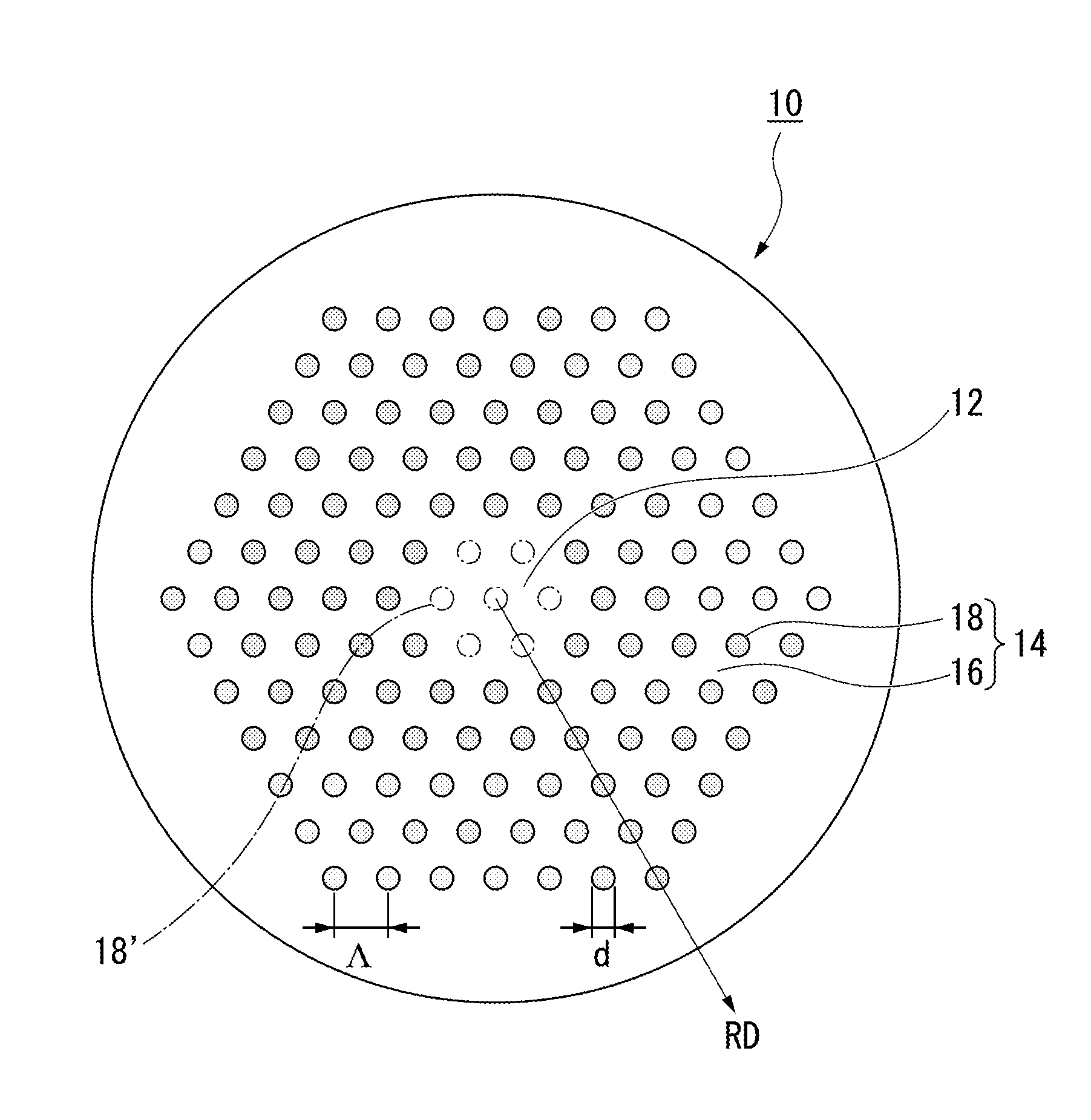
[0240]In Example 1, basically, the core area was as large as two layers (seven-cell core structure), and the first band gap was used as the permeation band.

[0241]Specifically, as shown in FIG. 5, Example 1 has a structure which is a two-layer equivalent core type, and has high refractive index scatterers periodically arrayed in a triangular grid shape.

[0242]In manufacturing the fiber, the target Λ was 11 μm, and the target Δ was 2.0%.

[0243]In addition, d was adjusted (approximately 1.8 μm) so that V became approximately 1.6.

[0244]Therefore, when the fiber is used at a wavelength of 1064 nm, the first band gap is used as the permeation band.

[0245]The material of the preform of the optical fiber mainly included silica glass, germanium-added silica glass was used as the material of the high refractive index scatterers, and the preform of the stacking structure was manufactured using the stack and draw method.

[0246]In addition, the preform of the stacking structure was spun while contro...

example 2

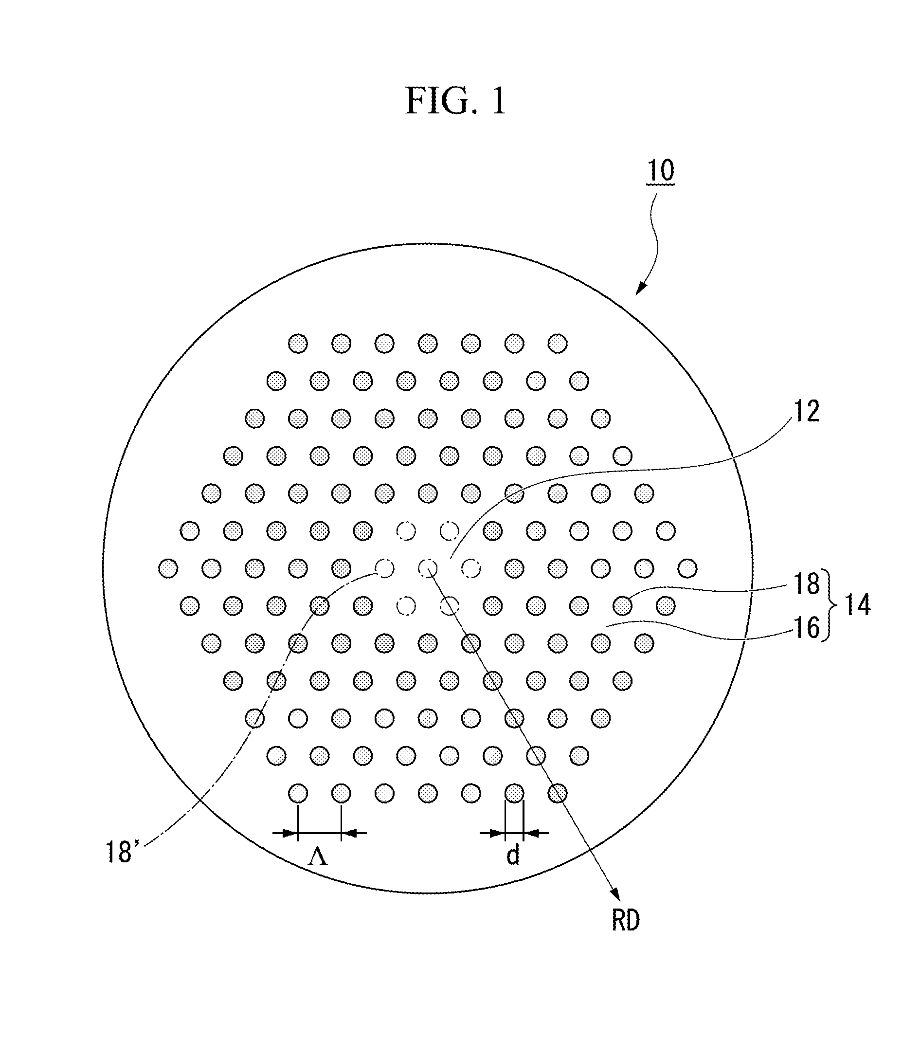
[0254]In Example 2, basically, similarly to Example 1, the core area was as large as two layers (seven-cell core structure).

[0255]The third band gap was used as the permeation band.

[0256]Specifically, as shown in FIG. 5, Example 2 has a structure which is a two-layer equivalent core type, and has high refractive index scatterers periodically arrayed in a triangular grid shape.

[0257]In manufacturing the fiber, the target Λ was 13 μm, and the target Δ was 2.5%.

[0258]In addition, d was adjusted (approximately 4.8 μm) so that V became approximately 4.65.

[0259]Therefore, when the fiber is used at a wavelength of 1064 nm, the third band gap is used as the permeation band.

[0260]The material of the preform of the optical fiber mainly included silica glass, germanium-added silica glass was used as the material of the high refractive index scatterers, and the preform of the stacking structure was manufactured using the stack and draw method.

[0261]The preform of the stacking structure was spun...

example 3

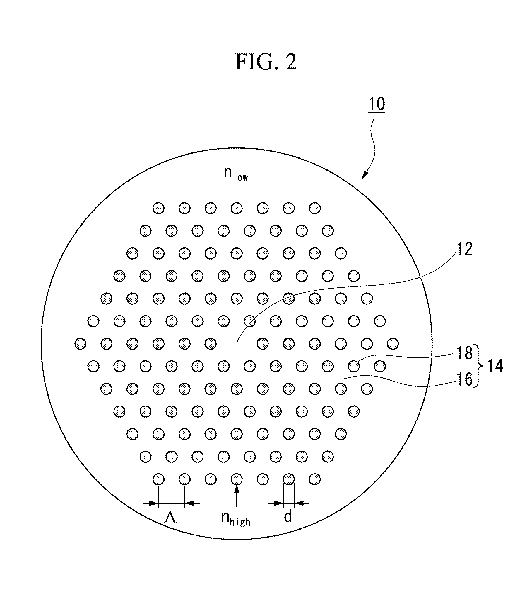
[0269]Example 3 is basically an example in which, similarly to Example 1, the core area was as large as two layers (seven-cell core structure), the first band gap was used as the permeation band, and the refractive index distribution of the high refractive index scatterers was not rectangular.

[0270]Specifically, as shown in FIG. 5, Example 3 has a structure which is a two-layer equivalent core type, and has high refractive index scatterers periodically arrayed in a triangular grid shape.

[0271]A fiber having the high refractive index scatterers with a non-step-form refractive index distribution (refer to FIG. 17) in which Λ was 11 μm, and Δ became 2.0% in terms of the step form was manufactured.

[0272]In addition, d was adjusted (approximately 1.8 μm) so that V became approximately 1.6.

[0273]Therefore, when the fiber is used at a wavelength of 1064 nm, the first band gap is used as the permeation band.

[0274]The material of the preform of the optical fiber mainly included silica glass,...


PUM

PropertyMeasurementUnit
cross-sectional areaaaaaaaaaaa
bending radiusaaaaaaaaaa
cross-sectional areaaaaaaaaaaa

Abstract

A solid photonic band gap fiber includes: a core area located at a central portion of a cross-section with respect to a longitudinal direction of the fiber, the core area being formed of a solid substance having a low refractive index; cladding areas having base portions formed of a solid substance having a low refractive index, the cladding areas surrounding the core area; and a plurality of fine high refractive index scatterers provided in the cladding areas, and disposed in a dispersed manner so as to surround the core area, the number of fine high refractive index scatterers being formed of a solid substance having a high refractive index, wherein in a state that the solid photonic band gap fiber is held at a predetermined bending radius, propagation in a high-order mode is suppressed by using a difference in a bending loss between a fundamental mode and the high-order mode, and only the fundamental mode is substantially propagated, the fundamental mode and the high-order mode being caused by bending.

Description

CROSS REFERENCE TO RELATED APPLICATIONS[0001]This application is a continuation application based on a PCT Patent Application No. PCT / JP2011 / 072138, filed Sep. 28, 2011, whose priority is claimed on Japanese Patent Application No. 2010-217798, filed Sep. 28, 2010, the entire content of which are hereby incorporated by reference.BACKGROUND OF THE INVENTION[0002]1. Field of the Invention[0003]The present invention relates to an optical fiber for which the effective core cross-sectional area is enlarged in order to transmit high-power light and the like, and particularly, to a microstructure fiber including a wholly solid structure having fine high refractive index scatterers disposed in a dispersed manner in cladding areas that surround a core area (solid photonic band gap fiber), and an optical fiber module having the optical fiber.[0004]Furthermore, the invention relates to a technique that maintains propagation of light in the optical fiber as single mode propagation, and enlarges ...

Claims


Application Information

Patent Timeline
Patent Type & Authority Applications(United States)
IPC IPC(8): G02B6/02
CPCG02B6/02347G02B6/0281G02B6/02009H01S3/06741
Inventor TANIGAWA, SHOJITAKENAGA, KATSUHIROKASHIWAGI, MASAHIROSAITOH, KUNIMASA
Owner THE FUJIKURA CABLE WORKS LTD
Why Eureka
Try Eureka