There are several major drawbacks to this standard
implant design.
These drawbacks are derived from the fact that the standard
implant design form is actually in very significant variance to the natural root form of human teeth.
This major discrepancy in the contour or emergence profile, as it is termed in
dentistry, of the crown that is fixed upon the
implant abutment (which fits into the head of the implant) in relation to the gums results in large gaps or spaces between the implant crown and the teeth on either side of it and prevents the optimal formation of the interdental papilla (gum tissue between the teeth).
These large open areas or gaps allow for food debris, plaque, and
pathogenic bacteria to accumulate between the implant crown and the natural teeth adjacent to it, making these areas very difficult for the patient to keep clean and requiring the patient to use special cleaning implements to try and maintain them free of food debris and plaque.
In many cases this situation over the long-term results in poor health of the gums, causing periodontal (gum)
disease of the adjacent teeth as well as documented cases of implant failure due to
crestal bone resorbtion.
Tensile forces are forces that are coronally directed along the
long axis of the implant and are not tolerated well by the implant.
Shear forces are off-axis forces or loads on the implant that have the potential to be most destructive to the integrity of the implant-bone complex.
Due to their single “root” design, standard implants placed in the
molar (posterior) areas of the mouth are most susceptible to the negative effects of shear off-axis forces.
Crater-shaped bone defects which are typically found clinically to form around the “heads” (top portion of the implant embedded in the bone) of these implants over time are suspected to be a result of such adverse loading.
The relatively narrow cross-sectional
diameter of the single “head” of most dental implants does not allow for the proper distribution of this load for
molar implants.
As noted above, vertical (compressive) loading forces are the forces best handled by standard dental implants, as opposed to shear (off-axis) loading forces which are much more damaging over the long term to the integrity and viability of the standard dental implants (and particularly standard posterior
molar implants) in the mouth.
All of the above presents significant challenges to the dental practitioner when attempting to replace these missing
posterior teeth with the standard
dental implant design.
Due to their single large cylindrical “root” form, the
anatomy of the upper and lower jaws can be particularly unsuitable to accommodate the standard
dental implant design in these molar regions.
This unsuitability of design is the case even more so in patients who have large maxillary sinuses in the upper jaw or crestal height resorbtion of the maxilla or mandible (a very common finding in patients who have previously lost their molars).
These procedures are costly and are associated with concomitant health risks to the patient.
Often these anatomical limitations may force the dentist to place the implants in a non-optimal location or if the limitations are severe, they may totally preclude the patient from receiving this restorative treatment option altogether.
The dentist also runs the general risk in many cases of perforating the
maxillary sinus (compromising its health), perforating the lingual or buccal plates of the mandible (causing infection and implant failure), or disturbing or partially severing the inferior alveolar nerve in its canal in the mandible (causing a temporary or permanent parasthesia) when attempting to place a standard posterior
dental implant.
This prior art is very limited in its design and incorporates as well significant structural defects that could compromise its short and long term viability in the mouth and could actually cause over time a
catastrophic failure of the components of its separate stages as will be explained below.
Additionally, the tools described in this prior art do not allow for the accurate, precise, and reproducible preparation of the implant site as well as the accurate, precise, and reproducible
assembly of the components of the implant within that site in a three-dimensional manner.
This is a significant drawback in the structural design of the prior art for the following reasons: As noted above, there are significant limitations on the maximum interdental (mesio-distal distance between the teeth) and bucco-lingual (width of the jawbone) dimensions of the implant site.
The
diameter of the “head” component that can typically be accommodated in this limited implant site for missing molar teeth without
puncturing this three-dimensional volume of the bone in both of the above two dimensions is itself quite limited.
By incorporating in its basic design a “root screw” that must of necessity be of smaller
diameter than the retention hole of the “head” component into which it slides through requires the “root screw” component of this prior art to be extremely “thin”, resulting in a critically insufficient diameter or girth for these “root screw” components.
As these “root screw” components are the primary structures of the implant that provide the retention, stability and load support for the entire implant, this design flaw is of critical importance and would jeopardize the long term and even short term viability of this
implant design in the mouth (as noted above, it is accepted in the dental field to always use larger diameter single “root screws” for posterior implants compared to anterior implants due to the greater forces normally placed on the posterior implants).
The inadequate diameter of these “root screws” is even more problematic when one considers the fact that all “root screw (s)” do not have a
solid core and in fact must contain an internal hollow shaft to accommodate the connector screw which threads into it.
This means that the thickness of the outer walls of the “root screw” design of this prior art must be extremely thin and would be very prone to fracture (resulting in complete failure of the implant) under even a minimal load.
Additionally, the very small diameter of the “root screw” components necessitated by the design of the prior art also necessitates that the single set of “connector screws” provided by the prior art to secure all three components (the “head”, “root screw” and
abutment components) to each other to be even thinner than the “root screws” (as they must thread inside them), which, over time, (or even on
initial load) could easily lead to their fracture under load.
This would cause a separation of these two components within the jawbone, resulting in the complete failure of this
implant design and a
nightmare scenario for the dental practitioner to have to deal with.
This design feature further limits the maximum possible diameter of the connector screws and also necessitates the further
thinning of the outer walls (which contain the connector screw) of the “root screw” components.
These design features even further increase the likelihood of the fracture and failure of these components, above and beyond what has already been noted, when these components would be placed under load in the posterior sections of the upper and lower jaws.
This protocol of waiting for healing for several months duration is especially applicable to posterior (molar) implants due to the poor
bone quality in these posterior regions of the jaws and the greater load these implants must support once they are placed under loading function (chewing on the crown atop their abutments).
This shifting and fixing in place of the shifted position of these components within the bone during healing may result, in the prior art, in a loss of parallelism of the “head” and “root screw” components of the prior art and therefore may not allow for the
insertion of the two internal sleeves or tube features described on the inferior aspect of the abutment stage of the prior art into the corresponding two retention shafts of the “head” and “root screw” components.
This would present an extreme problem for the dental practitioner to properly assemble the components of the prior art's implant and which might even necessitate the
surgical removal of the implant, a highly undesirable result.
If the shifting is minimal it still may require the dentist to use excessive force in order to screw down one or both of the connector screws through the now non-parallel shafts between these components.
The forceful screwing of these two connector screws into the non-parallel shafts may compromise the integrity of the implant of this prior art, as it will place undue stress on the components and surrounding bone, and may result in bone resorbtion (die-back) and long term failure of the prior art's implant.
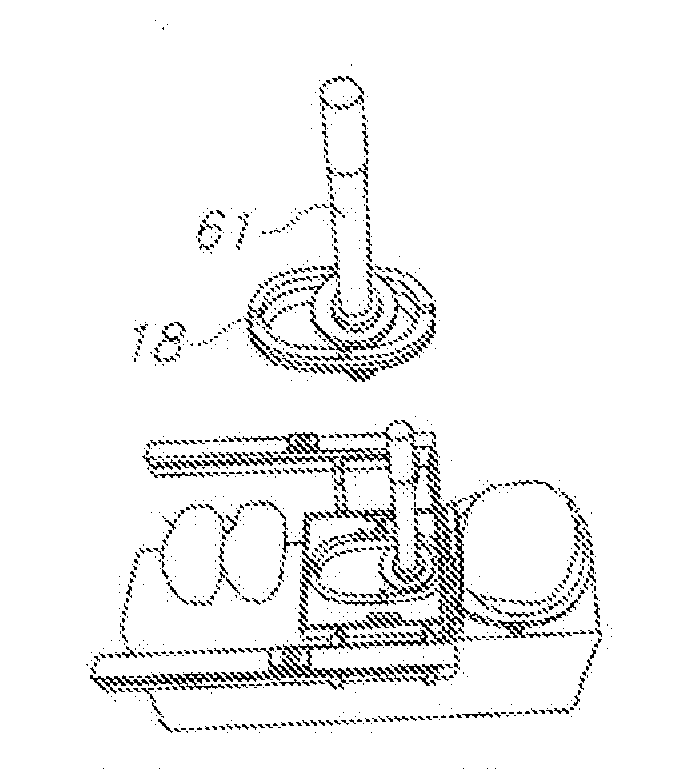
Drawbacks of the Surgical Tools: While WO Pat. App. No. 2006 / 082610 does describe a basic template guide for drilling the bore shafts to allow for the placement of the “root screw” components, its
surgical template does not allow for preparing an accurate and precise depth and position of the bone preparation of the “head” component, and so does not allow for the accurate and precise
insertion of these components in a reproducible fashion by the dental practitioner in the implant site.
This is due to the lack in this prior art of any form of clamping device to accurately and precisely fix the template over the implant site to allow for just such an accurate preparation of the bone at the implant site to receive both the “head” component and “root screw” components of the implant.
This prior art fails to achieve this basic requirement and so is impractical for the use of the dental practitioner who wishes to place implants with a high success rate.
WO Pat. No. 2006 / 082610 allows for the preparation and insertion of one and only one “head” stage form (component) in the implant site, and only for “multiple” rooted implants, a distinct
disadvantage.
A further major drawback of the entire prior art (including this particular prior art) is that they do not allow for surgical templates that allow for the placement of different mesio-distal length “heads”.
The prior art does describe one other alternate shape (elliptical) for the “head” stage form (component) but provides no means for preparing the implant site to accommodate this other shape, a serious drawback of the prior art.
Additionally, the cross-sectional shape of the particular “head” component described in this prior art for which it does provide a basic means for preparing the bone site to accommodate its form, does not conform to the natural cross-sectional form of any of the natural molars at the crestal height of the bone (the level of the implant-abutment interface, known in the dental field as the crucial “biological width” or attachment zone) and is therefore a poor choice of “head” form (component) from a biological perspective to implant into the posterior jawbones.
This design in fact results in a biomechanical
disadvantage over the previous art as it embodies a wider platform (known in the dental implant field as platform switching) for occlussal loading (chewing) which then narrows to the standard round cross-sectional diameter of a standard “head” of a standard dental implant.
This exaggerated platform switching design (compared to the other prior art) may actually lead to increased bone loss, known in the dental filed as “craterization” or “saucerization”, a well known deleterious consequence commonly found in the bone surrounding the “heads” of all the current prior art once the molar implants are placed under occlussal load for a sufficient period of time in the
oral cavity.
This prior art offers no features to adjust the location of the guide ring in any of the three axes, nor does it take into account the adjacent teeth, which, based on its design dimensions, would interfere with its placement between the adjacent teeth in close proximity to the surface of the intended implant site.
This design though, does not allow for the clamping of the device in the very common situation requiring dental implant restorations, of what is termed in the dental field as a “free-end
saddle” case.


