Controlling Fluid Flow Through An Assay Device

a technology of fluid flow and assay device, which is applied in the field of diagnostic assays, can solve the problems of difficult to meet all these requirements in one and the same assay, and many assays are limited by the speed, sample size and dimension of the device, so as to reduce the pressure gradient

Inactive Publication Date: 2013-08-15
ORTHO-CLINICAL DIAGNOSTICS
View PDF5 Cites 30 Cited by
  • Summary
  • Abstract
  • Description
  • Claims
  • Application Information

AI Technical Summary

Benefits of technology

[0012]One aspect of the invention is directed to an assay device, which includes: a liquid sample zone; a reagent zone downstream and in fluid communication with the sample zone containing a reagent material; a detection zone in fluid communication with the reagent zone, wherein the detection zone comprises a substrate and a first set of projections which extend substantially vertically from the substrate, wherein the projections have a height, cross-section and a distance between one another that defines a capillary space between the projections capable of generating capillary flow parallel to the substrate surface; and a wicking zone in fluid communication with the detection zone having a capacity to receive liquid sample flowing from the detection zone, wherein the wicking zone comprises a substrate and a second set of projections which extend substantially vertically from the substrate, wherein the projections have a height, cross-section and a distance between one another that defines a capillary space between the projections capable of generating capillary flow parallel to the substrate surface, wherein the wicking zone is rectangular in shape and the longer side of the rectangle extends in the direction of flow to thereby reduce the pressure gradient in the assay device which increases the total flow time of liquid sample compared to a wicking zone having equal length sides and same volume, and further wherein at least a portion of the second set of projections have at least one dimension selected from a diameter, a center-to-center spacing, or a gap between projections that is different from the first set of projections, and is selected to increase the total flow time of the sample through the device.

Problems solved by technology

Understandably it is difficult to meet all these requirements in one and the same assay.
In practice, many assays are limited by their speed.
However, it has been found that reducing the sample size and dimensions of the device provides inadequate conjugate in the detection zone and accordingly less signal that can be read by the instrument, in some instances up to a 5× lower signal and poor sensitivity.
The inadequate conjugate in the detection zone is believed to be due to reduced sample size and inefficient use of the sample in the device, amongst other conditions.
Another drawback of reducing dimensions is the width of the detection zone will also be reduced, again making less signal available that can be read by the instrument.

Method used


Image

  • Controlling Fluid Flow Through An Assay Device
  • Controlling Fluid Flow Through An Assay Device
  • Controlling Fluid Flow Through An Assay Device

Examples


examples

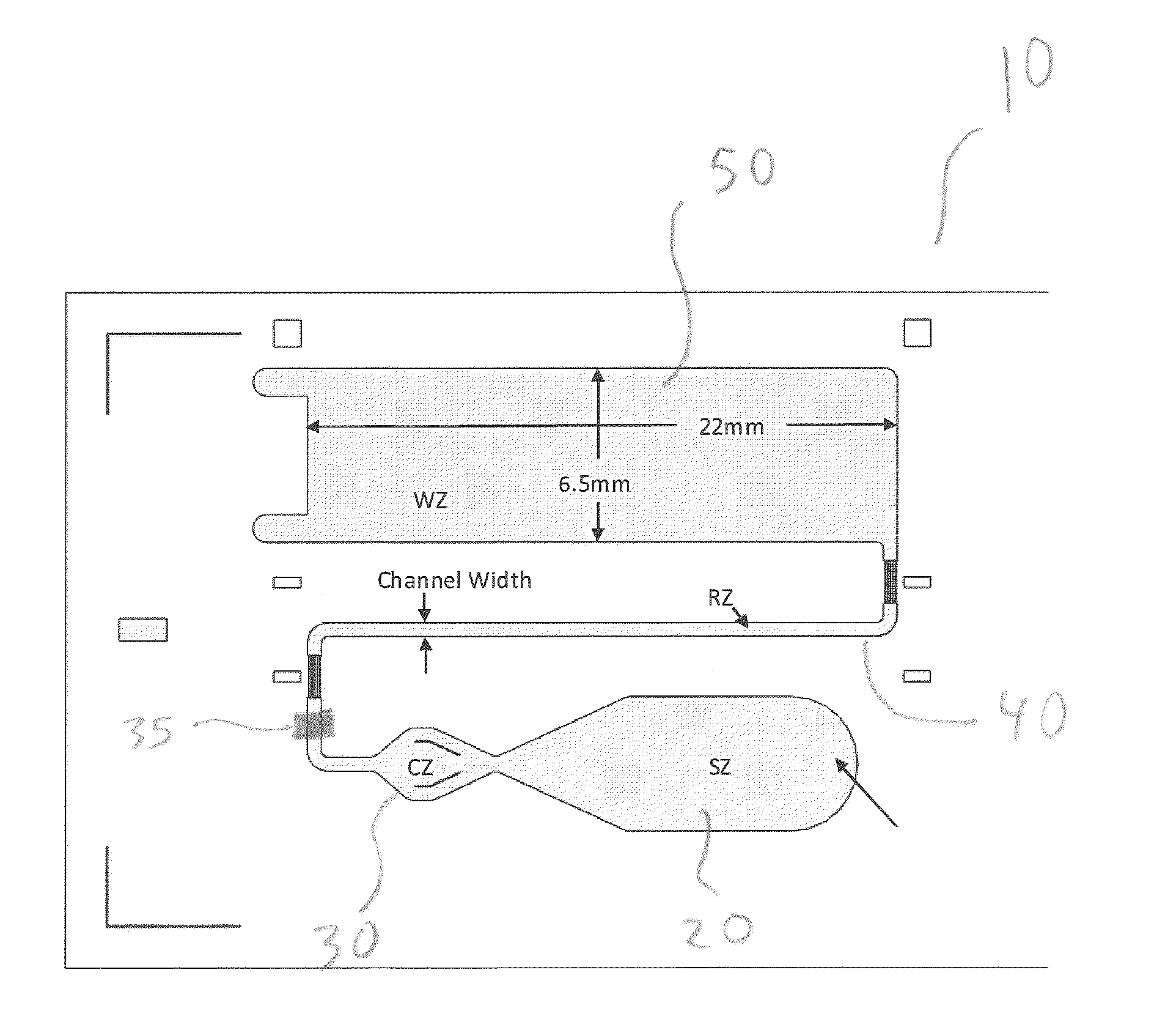
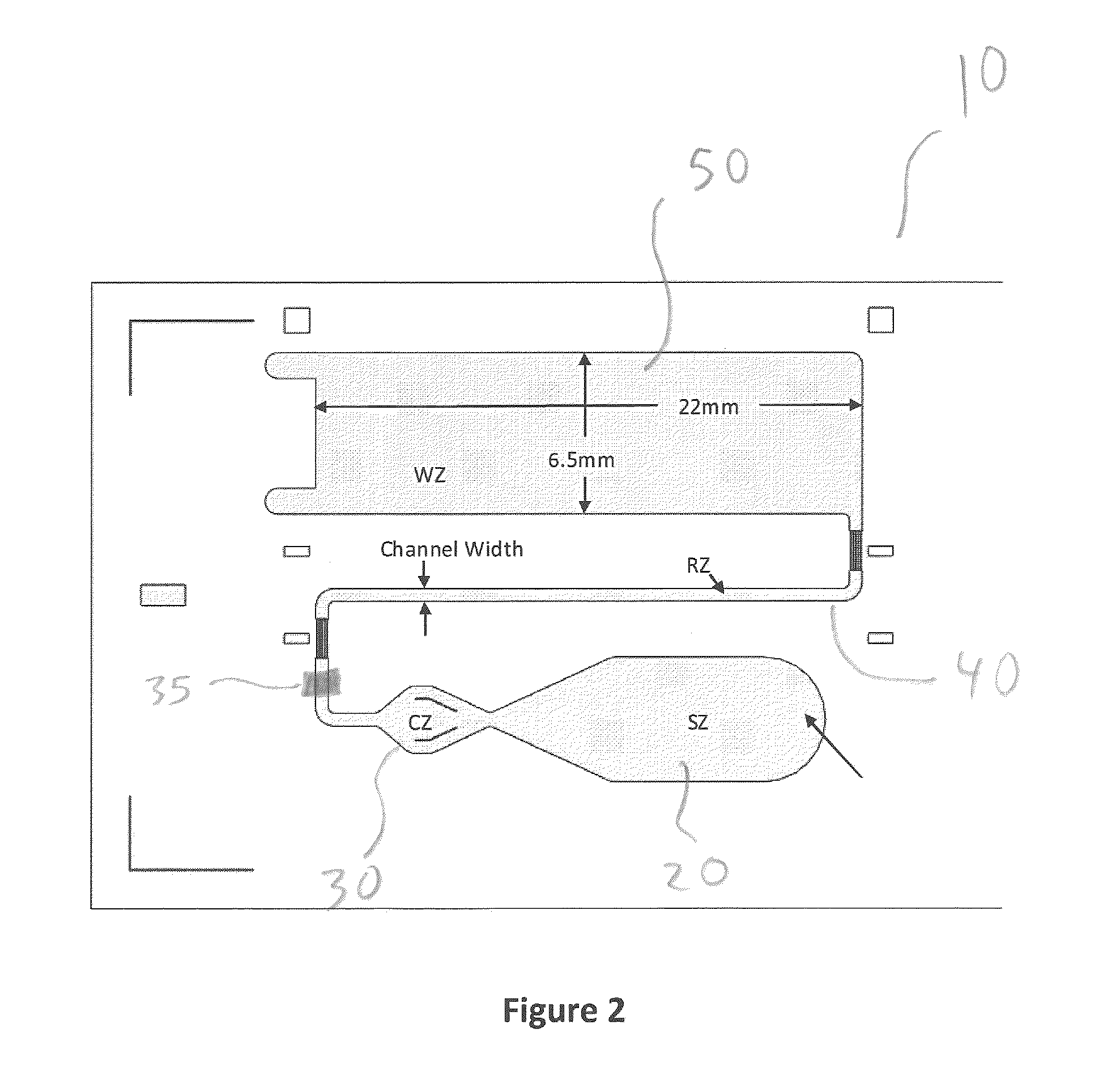
[0081]Plastic substrate chips made of Zeonor (Zeon, Japan) having oxidized dextran on the surface for covalently immobilization of proteins via Schiff base coupling were used. Fluorescently labeled Anti-NT-proBNP monoclonal antibody was deposited and dried to create a reagent zone. Anti-NT-proBNP monoclonal antibody was deposited and dried to create a detection zone. A small amount of Triton X-45 was deposited on the device to increase wettability of the sample for better capillary flow. Sample was added to the sample zone of the device and the capillary action of the micropillar array distributed the sample through the flow channel into the wicking zone. A typical assay time was about 10 minutes. The signal intensities from the fluorescently labeled complexes in the detection zone were recorded in a prototype line-illuminating fluorescence scanner. The results are shown in FIG. 8 described below.

[0082]An assay device having wicking zone dimensions of (R2.04) 10 mm×10 mm and an assa...


PUM

PropertyMeasurementUnit
total areaaaaaaaaaaa
diameteraaaaaaaaaa
diameteraaaaaaaaaa

Abstract

An assay device includes: a detection zone which includes a first set of projections which are capable of generating capillary flow. A wicking zone (WZ) has a capacity to receive liquid sample flowing from the detection zone and includes a second set of projections which are capable of generating capillary flow. The WZ is rectangular in shape and the longer side of the rectangle extends in the direction of flow to thereby reduce the pressure gradient in the assay device which increases the total flow time of liquid sample compared to a WZ having equal length sides and same volume. At least a portion of the second set of projections have at least one dimension selected from a diameter, a center-to-center spacing, or a gap between projections that is different from the first set of projections, and is selected to increase the total flow time of the sample.

Description

CROSS REFERENCE TO RELATED APPLICATIONS[0001]This patent application claims priority to U.S. Provisional Application No. 61 / 588,772, filed Jan. 20, 2012, the disclosure of which is incorporated by reference in its entirety.FIELD OF THE INVENTION[0002]The present invention relates to the field of diagnostic assays, and in particular to lateral flow assays where an analyte to be detected is present in a biological or non-biological sample.BACKGROUND[0003]Diagnostic assays are widespread and central for the diagnosis, treatment and management of many diseases. Different types of diagnostic assays have been developed over the years in order to simplify the detection of various analytes in clinical samples such as blood, serum, plasma, urine, saliva, tissue biopsies, stool, sputum, skin or throat swabs and tissue samples or processed tissue samples. These assays are frequently expected to give a fast and reliable result, while being easy to use and inexpensive to manufacture. Understanda...

Claims


Application Information

Patent Timeline
Patent Type & Authority Applications(United States)
IPC IPC(8): G01N33/543
CPCG01N33/54366G01N33/558A63F7/0628A63B71/04A63B69/36A63F2007/3005B01L2400/0406B01L3/50273B01L2400/086G01N33/54388
Inventor KANALEY, JAMES D.DING, ZHONGHOSIMER, PHILIP C.SCALICE, EDWARD R.DANIELSON, SUSANTOMASSO, DAVID A.WARREN, TIMOTHY C.
Owner ORTHO-CLINICAL DIAGNOSTICS
Why Eureka
Try Eureka