Three-Dimensional Wafer-Scale Batch-Micromachined Sensor and Method of Fabrication for the Same

a micromachined sensor and three-dimensional wafer technology, applied in the field of micro-scale spherical resonators, can solve the problems of high cost of hrg and inability to be carried by man

Active Publication Date: 2013-08-22
RGT UNIV OF CALIFORNIA
View PDF2 Cites 13 Cited by
  • Summary
  • Abstract
  • Description
  • Claims
  • Application Information

AI Technical Summary

Benefits of technology

[0009]Further, in the illustrated embodiments reference is made to glass or glassblowing as part of the fabrication steps. Again, wherever “glass” or “glassblowing” is referenced, it must be understood in this specification and its claims that any thermoplastic deformable material is intended to be included and the methods known for deforming the same. In the illustrated embodiments examples with Pyrex glass are provided. It must expressly be understood that the term “glass” includes within its scope other materials suitable for high temperature plastic deformation driven by pressure and surface tension forces (“glassblowing”). Specific examples are low thermal expansion glasses and glass-ceramics such as Zerodur®, ultralow expansion titania silicate glass, amorphous quartz (silica), and materials known in the art to be similar. Accordingly, the invention includes the use of materials in vibratory resonators other then silicon as the “glassblowing” substrate, e.g. silicon would not be compatible in combination with some of the higher temperature glasses. By way of illustration, titania silicate, fused quartz, graphite, and silicon carbide can be used as the substrate instead of silicon wafers. It is advantageous to choose a material for the substrate which matches the thermal expansion coefficient of the material used for gyroscope or sensor and also able to sustain the temperatures required for the thermoplastic deformation of structural material, such as in the “glassblowing” step. Glassblowing titania silicate spherical shells on etched quartz substrates may provide the highest performance gyroscope.
[0032]The illustrated embodiments further include the steps of chemically treating the shells to decrease roughness and improve performance of the microshell resonator gyroscope (MSRG) formed therefrom by polishing of an inner and outer surface of the shells by means of wet or vapor phase of processing.

Problems solved by technology

A disadvantage of the current technology for HRG is its extremely high cost, mainly due to a boutique manufacturing process.
Although conventional HRG is widely used for precision inertial navigation and guidance applications, it is not suitable for man portable application because of its size, weight and power (SWaP) metrics.

Method used


Image

  • Three-Dimensional Wafer-Scale Batch-Micromachined Sensor and Method of Fabrication for the Same
  • Three-Dimensional Wafer-Scale Batch-Micromachined Sensor and Method of Fabrication for the Same
  • Three-Dimensional Wafer-Scale Batch-Micromachined Sensor and Method of Fabrication for the Same

Examples


Embodiment Construction

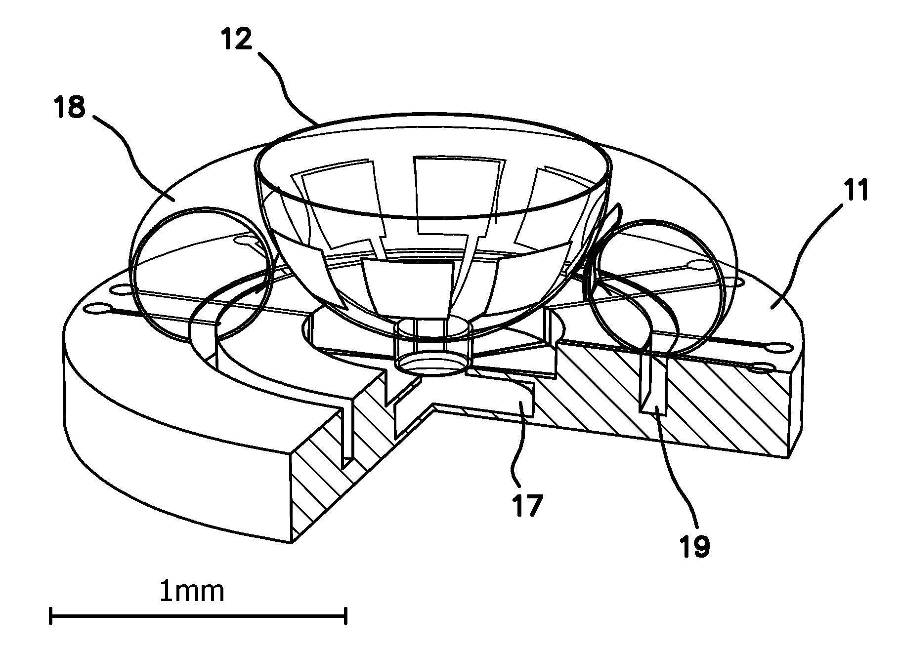
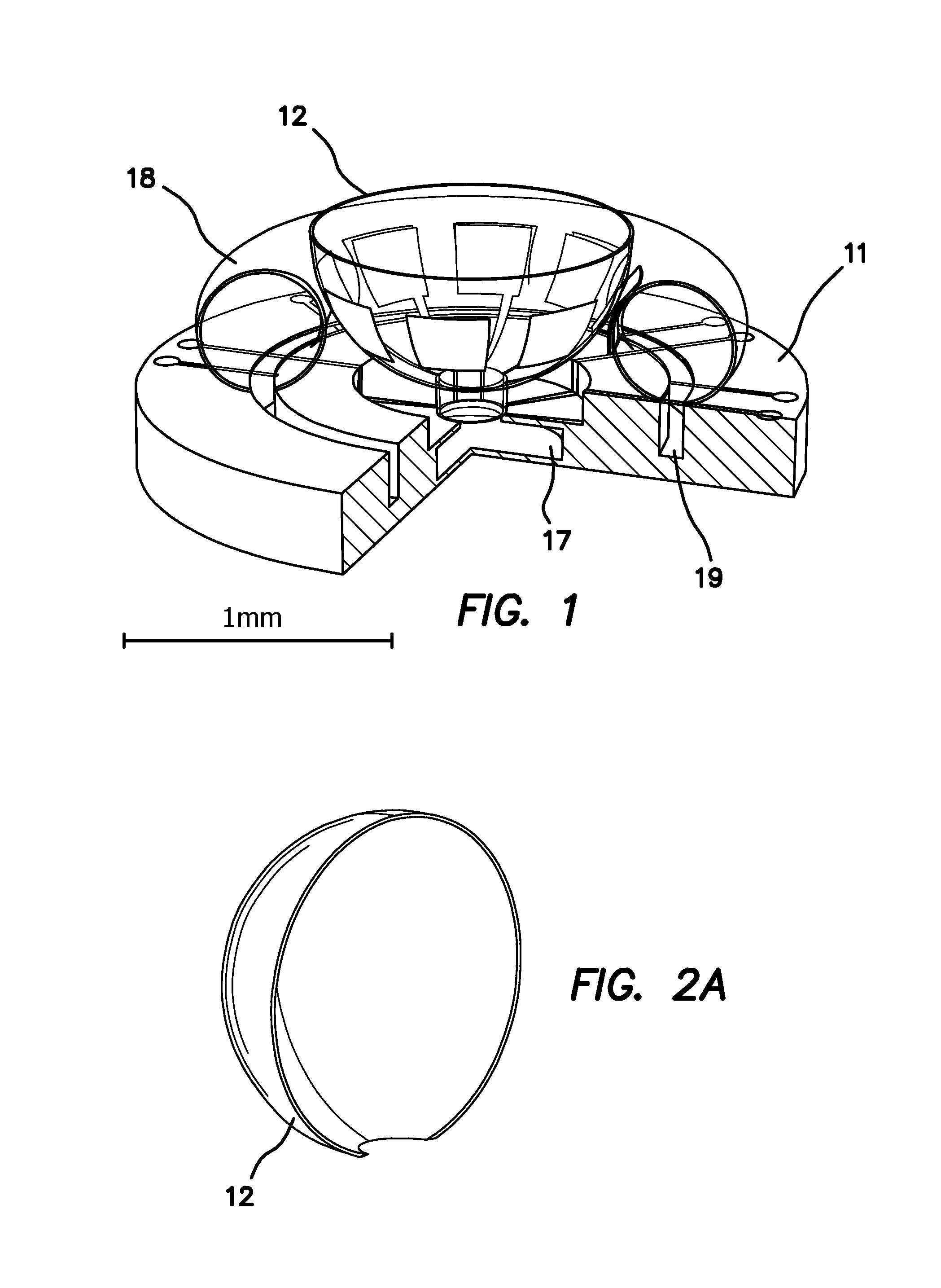
[0058]A three-dimensional wafer-scale batch-fabricated angle / angular rate microshell resonator gyroscope (MSRG) 10 with on-chip actuation and detection, as diagrammatically shown in FIG. 1. The various designs and fabrication methods for MSRG using extended glass-blowing techniques are also disclosed. These wafer-level techniques are not limited by the MSRG fabrication, but enable a broad class of novel three-dimensional multi-material resonant structures for inertial applications.

[0059]Three different structural implementations of the MSRG concept are shown in FIGS. 3a-3c. While these designs differ in resonant shell geometry and transduction mechanism, the main operational principle remains the same in each. The gyroscope operation is explained in detail below using an example of wine-glass MSRG 10 with spherical electrodes. Other possible configurations are also discussed, namely: “MSRG with three-dimensional transduction mechanism,” and “MSRG with separately fabricated electrode...


PUM

PropertyMeasurementUnit
diameteraaaaaaaaaa
diameteraaaaaaaaaa
diameteraaaaaaaaaa

Abstract

A vibratory sensor is fabricated as a three-dimensional batch-micromachined shell adapted to vibrate and support elastic wave propagation and wave precession in the shell or membrane and at least one driving electrode and preferably a plurality of driving electrodes directly or indirectly coupled to the shell to excite and sustain the elastic waves in the shell. The pattern of elastic waves is determined by the configuration of the driving electrode(s). At least one sensing electrode and preferably a plurality of sensing electrodes are provided to detect the precession of the elastic wave pattern in the shell. The rotation of the shell induces precession of the elastic wave pattern in the shell which is usable to measure the rotation angle or rate of the vibratory sensor.

Description

RELATED APPLICATIONS[0001]The present application is related to U.S. Provisional Patent Application, Ser. No. 61 / 250,849, filed on Oct. 12, 2009, which is incorporated herein by reference and to which priority is claimed pursuant to 35 USC 119.GOVERNMENT RIGHTS[0002]This invention was made with Government support under Grant No. 70NANB5H1235, awarded by the National Institute of Standards & Tech and the NAVY / Naval Surface Warfare Center Grant No. NOO 178-08-C-1 0 14. The Government has certain rights in this invention.BACKGROUND OF THE INVENTION[0003]1. Field of the Invention[0004]The invention relates to the field of batch fabricated micromachined gyroscopes and more particularly to batch fabricated micromachined rate integrating and angular rate gyroscopes and more generally to microscale spherical resonators.[0005]2. Description of the Prior Art[0006]The recent market survey of today's inertial sensors suggests the increasing demand for portable low-cost, and high-precision gyros...

Claims


Application Information

Patent Timeline
Patent Type & Authority Applications(United States)
IPC IPC(8): B29C44/02
CPCB29C44/022G01C19/5691B29C44/02G01C19/56
Inventor SHKEL, ANDREI M.TRUSOV, ALEXANDER A.PRIKHODKO, IGOR P.ZOTOV, SERGEI A.
Owner RGT UNIV OF CALIFORNIA
Why Eureka
Try Eureka